Double-barrel ball mill for massive cement

A ball mill and cement technology, applied in non-rotational vibration suppression, grain processing, etc., can solve the problems of increasing the economic cost of the ball mill, poor impact effect of cement blocks, and reduced grinding efficiency, so as to promote turning over, prevent serious wear, and reduce dust The effect of high grinding efficiency

Inactive Publication Date: 2017-09-15
殷志成
View PDF0 Cites 8 Cited by
  • Summary
  • Abstract
  • Description
  • Claims
  • Application Information

AI Technical Summary

Problems solved by technology

[0003] Existing cement ball mills generally adopt a single-barrel structure. Put the block cement and steel balls into the ball mill, and beat and crush the block cement through the turning of the steel balls. Since the steel balls are only turned over by the ball mill, when the cement inside the ball mill When there are many blocks, the rolling range of the steel balls is small, the impact on the cement blocks is not good, and the grinding efficiency is reduced; when the existing cement ball mill is working, a large amount of heat will be generated due to the repeated contact between the steel balls and the cement, which will cause the steel balls to be heated and worn seriously, increasing The economic cost of the ball mill

Method used


Image

  • Double-barrel ball mill for massive cement
  • Double-barrel ball mill for massive cement
  • Double-barrel ball mill for massive cement

Examples


Embodiment Construction

[0020] The following will clearly and completely describe the technical solutions in the embodiments of the present invention with reference to the accompanying drawings in the embodiments of the present invention. Obviously, the described embodiments are only some, not all, embodiments of the present invention. Based on the embodiments of the present invention, all other embodiments obtained by persons of ordinary skill in the art without making creative efforts belong to the protection scope of the present invention.

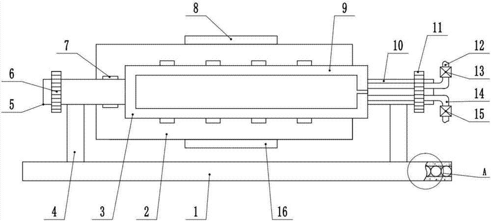
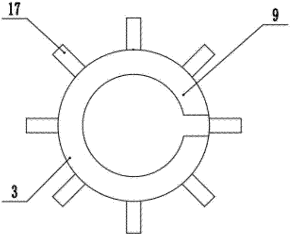
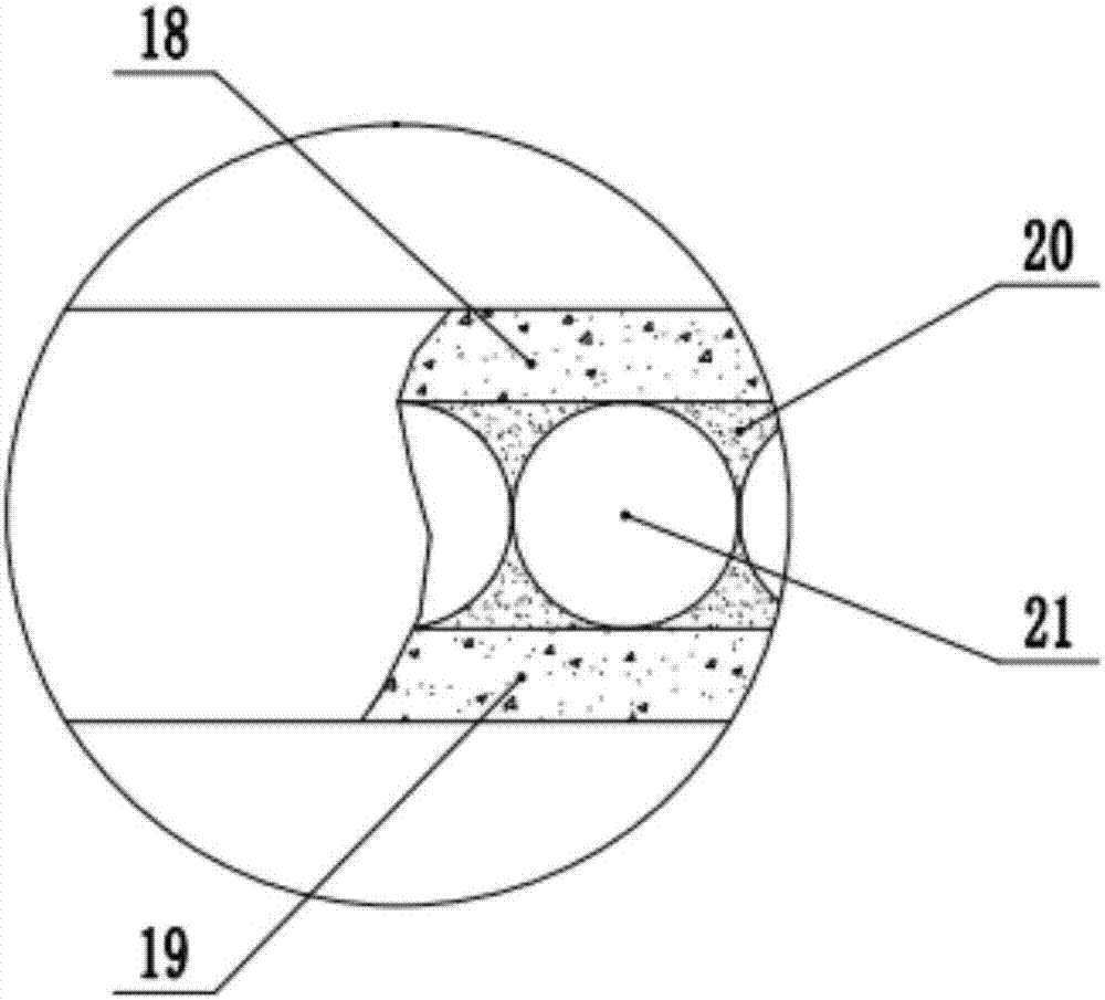
[0021] see Figure 1~4 , in an embodiment of the present invention, a block cement double-barrel ball mill includes a base 1, an outer barrel 2 and an inner barrel 3; two support frames 4 are symmetrically installed on the base 1, and the outer barrel 2 is sleeved on the The outside of the inner barrel 3 is described, the left side of the outer barrel 2 is fixedly connected with the first rotating shaft 5, the left end of the first rotating shaft 5 is rotatabl...


PUM


Abstract

The invention discloses a block cement double-barrel ball mill, which comprises a base, an outer barrel and an inner barrel; the outer barrel is sleeved on the outside of the inner barrel, and the left side of the outer barrel is fixedly connected with a first rotating shaft. The left end is rotatably installed on the support frame; the right end of the inner barrel is fixedly connected with a second rotating shaft, and the second rotating shaft is rotatably installed on the support frame on the right side of the base; the outside of the inner barrel is evenly provided with a number of turning plates; the inner barrel An annular cavity is also provided on the inner wall of the base; a first shock-absorbing layer and a second shock-absorbing layer are arranged inside the base. The present invention adopts the double-barrel design with opposite directions, and the grinding efficiency is high, and a turning plate is arranged on the surface of the inner barrel to promote the turning of the cement blocks and steel balls, and further improve the grinding efficiency; there is also an annular cavity inside the inner barrel , in order to pass cold water into the inner space of the outer bucket to cool down the temperature, and prevent the steel balls from being severely worn when heated; a shock-absorbing base is also provided to improve the stability of the device.

Description

technical field [0001] The invention relates to cement processing equipment, in particular to a block cement double-barrel ball mill. Background technique [0002] In the cement production process, the blocky cement clinker needs to be ground to a suitable particle size to form a certain particle gradation, so as to increase its hydration area, accelerate the hydration rate, and meet the cement paste coagulation and hardening requirements. Blocky cement clinker is generally ground with a cement ball mill. Cement ball mill is the core equipment of cement plant, the final process of cement manufacturing, and the process that consumes the most power. [0003] Existing cement ball mills generally adopt a single-barrel structure. Put the block cement and steel balls into the ball mill, and beat and crush the block cement through the turning of the steel balls. Since the steel balls are only turned over by the ball mill, when the cement inside the ball mill When there are many b...

Claims


Application Information

Patent Timeline
Patent Type & Authority Applications(China)
IPC IPC(8): B02C17/10B02C17/18B02C17/24F16F15/02F16F15/08
CPCB02C17/10B02C17/18B02C17/24F16F15/02F16F15/08
Inventor 殷志成
Owner 殷志成
Why Eureka
Try Eureka