
Simple bending device

A bending device and simple technology, applied in the coating, epoxy resin coating and other directions, can solve the problems of inability to realize the bending of copper pipes and the inability to adjust the bending angle of copper pipes, and achieve simple structure, reasonable design and convenient operation. Effect

Inactive Publication Date: 2017-09-15
宁波奇尘电子科技有限公司
View PDF9 Cites 7 Cited by
  • Summary
  • Abstract
  • Description
  • Claims
  • Application Information

AI Technical Summary

Problems solved by technology

[0003] But the above-mentioned prior art also has the following deficiencies: the position of the positioning through hole can only be adjusted to the set angle by moving the lever, but the bending angle of the copper tube cannot be adjusted, and the copper tube cannot be folded in multiple places. bend

Method used


Image

  • Simple bending device
  • Simple bending device
  • Simple bending device

Examples


Embodiment 1

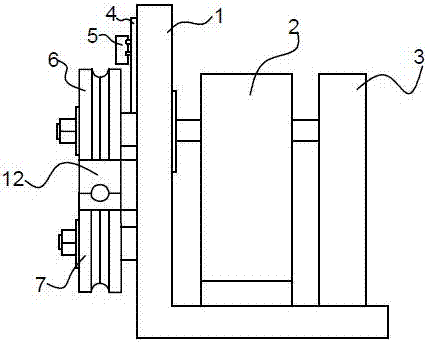
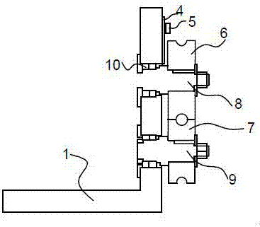
[0023] Such as Figure 1-3 As shown, a simple bending device includes a frame 1, a combination wheel placed on the frame 1, and a reducer 2 connected to the frame 1, the frame 1 is L-shaped, and the reducer 2 is placed on On the step surface of the frame 1, the combined wheels are placed on the side of the frame 1, and the combined wheels are connected by a shaft when placed, and the shaft passes through the frame 1 to communicate with the reducer 2, and one end of the reducer 2 is provided with a motor 3.

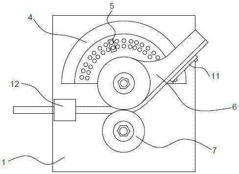
[0024] The lower end of the frame 1 is provided with anti-slip lines, and the side surface of the frame 1 is provided with a dial 4 for measuring the bending angle. The circle of the dial 4 coincides with the center of the combination wheel. Occasionally, the equipment will vibrate, or be displaced anyway, which will affect the operation of the device. The dial 4 is provided on the frame 1 to accurately obtain the bending angle during the bending process, so that the bendi...

Embodiment 2

[0034] Such as Figure 1-3 As shown, a simple bending device, in actual work, one end of the pipe piece passes through the guide block 12 on the frame 1 in sequence, and then enters the arc groove on the upper roller 6 and the lower roller 7, and passes through the upper roller 6 Interact with the lower roller 7 to support the pipe, and then use the pressure plate 11 provided on the upper roller 6 to fix it by tightening the bolts, and then hang the upper stop block 5 on the column row according to the required bending angle, as the upper roller 6 When rotating, bend the pipe fitting to a certain angle, the upper roller 6 will hit the upper limit block 5, stop the upper roller 6 from continuing to rotate, turn on the motor 3 when rotating, and reduce the speed through the reducer 2 to prevent excessive speed from causing The pipe is broken directly. When the upper roller 6 rotates, it drives the pendant to bend along with the arc of the upper roller 6, thereby driving the lowe...


PUM


Abstract

The invention provides a simple bending device. The simple bending device comprises a frame, a combination wheel placed on the frame, and a speed reducer connected with the frame; the frame is L-shaped; the speed reducer is placed on a step surface of the frame; the combination wheel is placed on the side surface of the frame, and is connected through a shaft during placing; the shaft penetrates through the frame to communicate with the speed reducer; and a motor is arranged at one end of the speed reducer. The simple bending device is simple in structure and convenient in operation, can perform positioned bending within 180 degrees according to angles, and quickly bends pipe-shaped parts to improve the production efficiency; bent pipe fittings are high in precision, not easy to drape and high in generality; and the simple bending device can bend workpieces with different sizes and different specifications, is low in cost, is additionally provided with a wear resistant coating layer for improving the durability, and prolongs the service life.

Description

technical field [0001] The invention relates to a simple bending device, in particular to a simple bending device. Background technique [0002] In the prior art, the invention patent application with the publication number CN104128401A discloses a manual copper pipe bending device, which includes a block-shaped bending body, and an arc-shaped forming arc groove is provided on the top of the bending body. The bottom of the bending main body is provided with a straight straight groove, the center of the bending body is provided with a rotation through hole, and the two sides of the straight groove are respectively provided with a positioning through hole. The user can put the strip-shaped copper tube into the forming arc groove in advance, and directly move the lever in the straight groove, so that the bending body rotates around the rotation hole until the lever moves to the Locate where the through holes are located. [0003] But the above-mentioned prior art also has the...

Claims


Application Information

Patent Timeline
Patent Type & Authority Applications(China)
IPC IPC(8): B21D7/024C09D163/00C09D127/12C09D7/12
CPCB21D7/024C08K2201/014C08L2205/035C09D163/00C08L27/12C08L33/08C08K13/02C08K5/5419C08K5/098C08K3/36C08K3/04
Inventor 叶力黄崇军
Owner 宁波奇尘电子科技有限公司
Learn More