Wall face grinding device for architectural decoration and finishing

A construction and grinding mechanism technology, applied in grinding/polishing safety devices, machine tools suitable for grinding workpiece planes, grinding machines, etc., can solve the problems of large space occupation, difficult handling, low grinding efficiency, etc. The effect of low maintenance cost, reduced space occupation, and reduced equipment investment

Inactive Publication Date: 2017-09-15
广东中创建设有限公司
View PDF5 Cites 9 Cited by
  • Summary
  • Abstract
  • Description
  • Claims
  • Application Information

AI Technical Summary

Problems solved by technology

In the past, the wall surface was polished by hand, which was not only low in efficiency, but also labor-intensive and time-consuming. The problem existing in the existing wall grinding machine is that it will cause dust to fly during the grinding process, which not only makes the working environment worse, but also greatly endangers the health of the operator, and it is large in size, difficult to carry, and takes up space The problem of large size and poor dust tightness

Method used


Image

  • Wall face grinding device for architectural decoration and finishing
  • Wall face grinding device for architectural decoration and finishing
  • Wall face grinding device for architectural decoration and finishing

Examples


Embodiment Construction

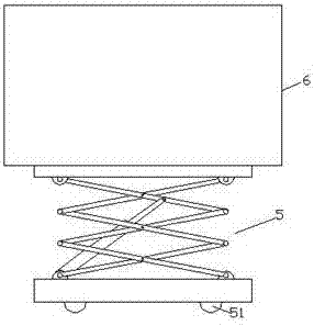
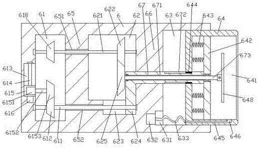
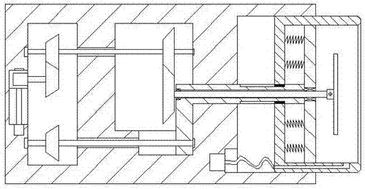
[0021] Such as Figure 1-Figure 5 As shown, a wall grinding device for building decoration of the present invention includes a scissor lift frame 5 and a grinding mechanism 6 installed on the top of the scissor lift frame 5, and the inside of the right end surface of the grinding mechanism 6 is A storage tank 63 is provided, and the storage tank 63 is slidably connected with an airtight sleeve 64. The airtight sleeve 64 is provided with a grinding chamber 641, and the grinding mechanism 6 on the left side of the storage tank 63 is provided with a transmission chamber 62. A first partition 66 is provided between the transmission chamber 62 and the storage tank 63, and a driving chamber 61 is provided in the grinding mechanism 6 on the left side of the transmission chamber 62, and the driving chamber 61 is connected to the storage tank 63. A second partition 65 is provided between the transmission chambers 62, and a first sliding groove 623 is provided on the inner bottom wall o...


PUM


Abstract

The invention discloses a wall face grinding device for architectural decoration and finishing. The wall face grinding device comprises a shear type lifting frame and a grinding mechanism mounted at the top of the shear type lifting frame. A storage groove is formed in the right end face of the grinding mechanism and connected with a closed sleeve in a sliding fit manner. A grinding cavity is formed in the closed sleeve. A transmission cavity is formed in the position, on the left side of the storage groove, in the grinding mechanism. A first partition plate is arranged between the transmission cavity and the storage groove. A drive cavity is formed in the position, on the left side of the transmission cavity, in the grinding mechanism. A second partition plate is arranged between the drive cavity and the transmission cavity. A first sliding groove is formed in the bottom wall in the transmission cavity. A connecting rod extending towards the left side and the right side is connected in the first partition plate in a sliding fit manner. The extending segment of the right side of the connecting rod stretches into the storage groove and penetrates the closed sleeve to extend into the grinding cavity. A supporting plate is fixedly arranged at the extending tail end of the right side of the connecting rod. A first through hole extending left and right is formed in the connecting rod. The wall face grinding device is simple in structure, reasonable in design and high in closing effect, dust flying is avoided, the occupied space can be reduced, and the manufacturing and maintaining cost is low.

Description

technical field [0001] The invention relates to the technical field of building construction equipment, and relates to a wall grinding device for building decoration. Background technique [0002] In the process of building construction or decoration, in order to make the flatness of the building wall higher and the surface more detailed and uniform, it is often necessary to polish the wall. In the past, the wall surface was polished by hand, which was not only low in efficiency, but also labor-intensive and time-consuming. The problem existing in the existing wall grinding machine is that it will cause dust to fly during the grinding process, which not only makes the working environment worse, but also greatly endangers the health of the operator, and it is large in size, difficult to carry, and takes up space Larger and poor dust tightness. Contents of the invention [0003] The technical problem to be solved by the present invention is to provide a wall grinding devic...

Claims


Application Information

Patent Timeline
Patent Type & Authority Applications(China)
IPC IPC(8): B24B7/18B24B55/06
CPCB24B7/182B24B55/06
Inventor 何水明
Owner 广东中创建设有限公司
Why Eureka
Try Eureka