
Entity wire frame modeling device

A wireframe and entity technology, applied in manufacturing auxiliary devices, coating devices, processing data acquisition/processing, etc., can solve troublesome and unsuitable problems such as integrated modeling of large solid wireframes, and achieve reduced friction and occupied volume small, stability-enhancing effect

Inactive Publication Date: 2017-09-15
HUAIYIN INSTITUTE OF TECHNOLOGY
View PDF2 Cites 0 Cited by
  • Summary
  • Abstract
  • Description
  • Claims
  • Application Information

AI Technical Summary

Problems solved by technology

[0002] 3D printing technology is becoming more and more mature, using computer data model for parameter control to realize layer-by-layer stacking printing modeling, but when performing solid wireframe modeling, traditional 3D printing technology has limitations, and general 3D printing devices are only suitable for For modeling printing of small items, when printing large objects or wireframes, it needs to be printed in sections and then stitched together, causing trouble, or a large-scale dedicated 3D printing device requires a large spatial range of displacement when working , to drive the discharge port to move, although it can adapt to general large-scale printing, but due to the need for assembly and coordination of large accessories such as positioning mobile frames, it will be subject to more restrictions, and it is not suitable for the integrated modeling of large solid wireframes

Method used


Image

  • Entity wire frame modeling device
  • Entity wire frame modeling device
  • Entity wire frame modeling device

Examples


Embodiment Construction

[0021] The present invention will be further described in detail below with reference to the drawings and specific embodiments.

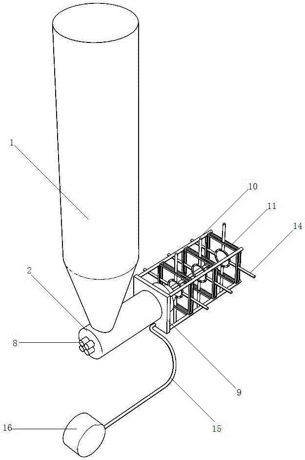
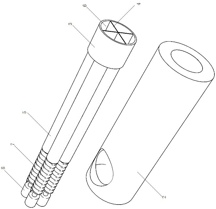
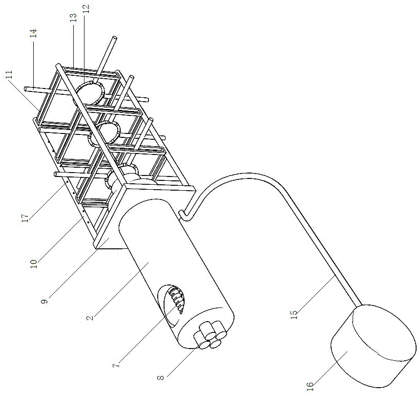
[0022] Such as Figure 1-7 As shown, the physical wire-frame modeling device includes a melt supply device 1, an extrusion mechanism, and a shaping mechanism; the extrusion mechanism includes a housing 2, and the discharge port of the melt supply device 1 is connected to the rear of the housing 2; the housing 2 The front end is plugged and connected with the model head 3; the model head 3 is a tubular structure, and the partition 4 arranged in the radial direction is evenly distributed in the model head 3; the partition 4 divides the interior of the model head 3 into a plurality of fan-shaped holes 6 evenly; A screw extruding device is installed in the housing 2; the screw extruding device includes a plurality of stacked feeding pipes 5; the number of the feeding pipes 5 and the fan-shaped holes 6 are the same and they are connected in one-to-one corre...


PUM


Abstract

The invention discloses an entity wire frame modeling device, and relates to the technical field of entity wire frame modeling. The device comprises a melt supply device, an extruding mechanism and a form fixing mechanism; the extruding mechanism comprises a shell, the front end of the shell is connected with a model head in an inserted manner, the screw extruding device comprises multiple feeding pipes connected in a stacked manner, spiral rods are connected with the interiors of the feeding pipes in a matched manner, the rear ends of the spiral rods penetrate the rear end of the shell in a seal manner and are connected with a motor, the form fixing mechanism comprises a square base fixedly connected with the front of the shell in a sleeving manner, multiple following clamping devices are arranged in front of the model head side by side, connecting rods are vertically fixed to the four right-angle positions of the square base, each following clamping device comprises a square frame fixedly connected with the connecting rods, and a tightening ring corresponding to the model head is arranged in the square frame. The device has the beneficial effects that integral modeling of the large entity wire frame is achieved, the structural size is small, and practicability is high.

Description

Technical field [0001] The invention relates to the technical field of solid wire frame modeling. Background technique [0002] 3D printing technology is becoming mature, using computer data models for parameter control to achieve layer-by-layer printing modeling. When performing solid wireframe modeling, traditional 3D printing technology has limitations, and general 3D printing devices are only suitable for The modeling printing of small items, large objects or wireframe modeling, requires segmented printing and then splicing, causing trouble, or a large dedicated 3D printing device requires a large spatial range of displacement when working , Drive the discharge port to move, although it can be adapted to general large-scale printing, but due to the need to assemble and cooperate with large-scale accessories such as positioning mobile racks, it will be subject to more restrictions and is not suitable for the integrated modeling of large-scale solid wire frames. In the solid w...

Claims


Application Information

Patent Timeline
Patent Type & Authority Applications(China)
IPC IPC(8): B29C64/209B29C64/393B29C64/30B33Y30/00B33Y50/02
CPCB33Y30/00B33Y50/02
Inventor 张光祥何艳婷吕艳张志强
Owner HUAIYIN INSTITUTE OF TECHNOLOGY
Learn More