Servo lifting roller machine

A rolling bed and servo motor technology, which is applied in the field of lifting rolling bed, can solve the problems of large space occupation of the lifting mechanism, large replacement man-hours, consumption, etc., and achieve the effects of ensuring the stability of the lifting, reducing the occupied area, and convenient installation and debugging

Active Publication Date: 2017-09-15
东风设备制造有限公司
View PDF11 Cites 0 Cited by
  • Summary
  • Abstract
  • Description
  • Claims
  • Application Information

AI Technical Summary

Problems solved by technology

This kind of lifting structure has the following technical problems: 1. When different types of car bodies are required for continuous processing, different types of car bodies need different height stations, so the rolling bed needs to be quickly lifted to different heights, while in this invention It is necessary to replace the lifting arm, which will not only consume a lot of replacement man-hours, but also be unfavorable and require a new structural design of the lifting arm; Under working conditions, it is necessary to dig a pit in the factory building to install the lifting mechanism, which is not conducive to the construction of the roller bed production line
This kind of invention also has the following technical problems: 1. When different types of car bodies are required for continuous processing, different types of car bodies require different height stations, so the rolling bed needs to be quickly lifted to different heights, while in this invention It is necessary to replace the lifting arm, which will not only consume a lot of replacement man-hours, but also be unfavorable and require a new structural design of the lifting arm; Under working conditions, it is necessary to dig a pit in the factory building to install the lifting mechanism, which is not conducive to the construction of the roller bed production line
This utility model has the following technical problems: 1. When different types of car bodies are required for continuous processing, different types of car bodies require different height stations, so the rolling bed needs to be quickly lifted to different heights, while in this invention it is necessary to Replacing the lifting arm will not only consume a lot of man-hours for replacement, but also is unfavorable and requires a new structural design of the lifting arm; Under the circumstances, it is necessary to dig a pit in the factory building to install the lifting mechanism, which is not conducive to the construction of the roller bed production line

Method used


Image

  • Servo lifting roller machine
  • Servo lifting roller machine
  • Servo lifting roller machine

Examples


Embodiment Construction

[0025] The preferred embodiments of the present invention will be described below in conjunction with the accompanying drawings. It should be understood that the preferred embodiments described here are only used to illustrate and explain the present invention, and are not intended to limit the present invention.

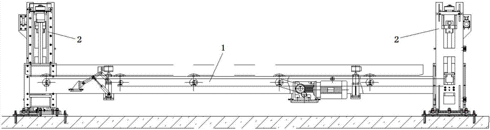
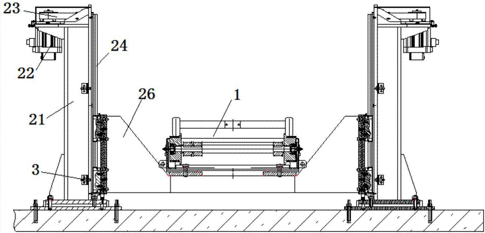
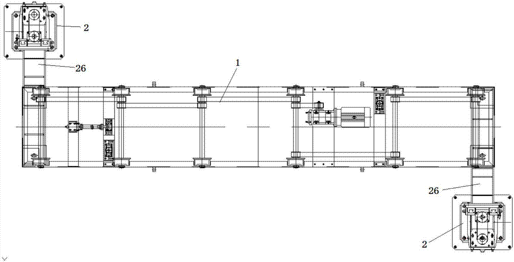
[0026] It can be seen from the accompanying drawings of the description of the present invention that a servo lifting roller bed of the present invention includes a horizontal conveying roller bed 1 and a servo lifting device 2 for lifting the horizontal conveying roller bed 1 in the vertical direction. The servo lifting device 2 includes at least two , and arranged symmetrically with respect to the central axis of the horizontal conveying roller bed 1; each servo lifting device 2 includes a vertical base 21, a servo motor 22, a guide rail slider mechanism 24, a ball screw 25 and a lifting bracket 26; The guide rail of block mechanism 24 and the leading screw of ball...


PUM


Abstract

The invention discloses a servo lifting roller machine. The servo lifting roller machine comprises a horizontal conveying roller machine and a servo lifting device; the servo lifting device comprises a vertical base, a servo motor, a guide rail slide block mechanism, a ball screw and a lifting bracket; the guide rail slide block mechanism and the roll screw are fixedly connected with the vertical base in the vertical direction; a fixed end of the servo motor is fixedly connected with the vertical base, and an output end of the servo motor is connected with a driving screw rod of the ball screw; the lifting bracket is connected with a slide block of the guide rail slide block mechanism and a driven nut of the ball screw; and the horizontal conveying roller machine is fixedly connected with the lifting bracket. The servo lifting roller machine is simple in structure and convenient in installation and debugging, effectively reduces the occupied area of a roller machine lifting mechanism through preventing use of a mechanical swing rod lifting or cam lifting structure, and can realize quick lifting in limited space.

Description

technical field [0001] The invention relates to a lifting roller bed, which belongs to the technical field of conveying and positioning forming stations of a body-in-white welding line, and in particular relates to a servo lifting roller bed. Background technique [0002] At present, in the transportation and positioning forming process of the domestic body-in-white welding line, the lifting roller bed is usually used for the rapid and automatic production and processing of the body. The lifting roller bed in the prior art mainly uses a common motor to drive the machine. Swing rod type lifting or cam type lifting has complex structure, inconvenient maintenance, and takes up a lot of space at the bottom. [0003] For example, a high-speed roller bed is disclosed in the Chinese invention patent specification CN103662695A, which includes a base, wherein the base is provided with a vertical lifting mechanism, the upper end of the vertical lifting mechanism forms a supporting sur...

Claims


Application Information

Patent Timeline
Patent Type & Authority Applications(China)
IPC IPC(8): B65G13/12
CPCB65G13/12Y02P70/10
Inventor 李翔刘湘庆张军张印
Owner 东风设备制造有限公司
Why Eureka
Try Eureka