
Rubber hose reel device with volatile gas recycling function

A volatile gas, rubber hose technology, applied in distribution devices, special distribution devices, liquid distribution, transportation or transfer devices, etc., can solve the problems of failing to meet the requirements of regulations and technical specifications, unable to play oil and gas, separation, etc., to achieve suitable In the promotion and implementation, improve the efficiency of operation, the effect of easy to use

Active Publication Date: 2017-09-15
正星科技股份有限公司
View PDF9 Cites 1 Cited by
  • Summary
  • Abstract
  • Description
  • Claims
  • Application Information

AI Technical Summary

Problems solved by technology

[0003] As the country pays more and more attention to environmental protection issues, it is required that gas stations must be equipped with oil and gas recovery systems. Although the existing rubber hose reel device can meet the business needs of gas stations, it cannot play the role of oil and gas separation, and cannot meet relevant regulations and technical specifications. requirements

Method used


Image

  • Rubber hose reel device with volatile gas recycling function
  • Rubber hose reel device with volatile gas recycling function
  • Rubber hose reel device with volatile gas recycling function

Examples


Embodiment 1

[0030] In this embodiment, the recovery of oil vapor during fuel filling at a gas station is taken as an example.

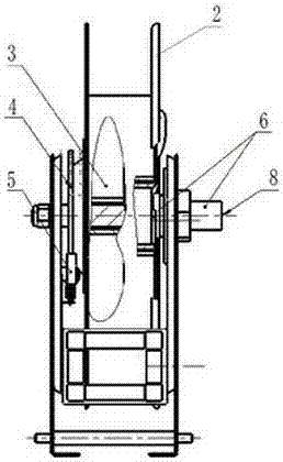
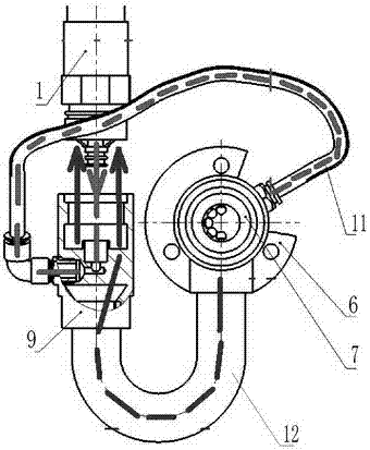
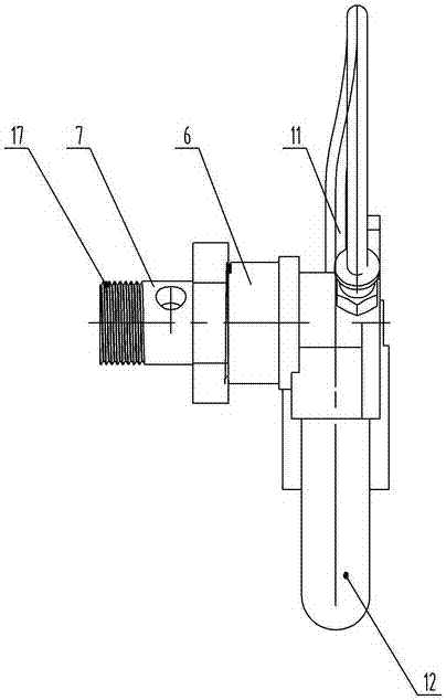
[0031] see Figure 1-8 , in the figure ( figure 2 The direction of the middle arrow indicates the flow direction of gas or liquid), the rubber hose reel device of the present invention includes a rubber hose, a reel 2, a coil spring 3, a limit mechanism composed of a ratchet 4 and a pawl 5, and a valve body, wherein the rubber hose is wound on the reel On the disk, the liquid output port of the hose is connected to the oil gun, and the valve body includes a valve seat 6 and a valve core 7, and the valve core is provided with an oil inlet 8. After the user lifts the gun, stretch the rubber hose and oil gun outward, and the reel rotates accordingly; when it is stretched to the vicinity of the refueling position, the standby pawl snaps into the tooth groove of the ratchet wheel, and the rubber hose is no longer retracted and pre-tensioned by the built-in coil spri...


PUM


Abstract

The invention relates to a rubber hose reel device. The rubber hose reel device comprises a rubber hose, a reel, a coil spring, a ratchet wheel limiting mechanism and a valve body; the rubber hose is wound on the reel, and the liquid outlet end of the rubber hose is connected with an oil gun; the valve body comprises a valve seat and a valve core, and the valve core is provided with a liquid inlet; and the rubber hose is a coaxial double-layer rubber hose comprising a core cavity and an interlayer cavity, the core cavity is a gas path, and the interlayer cavity is a liquid path. The rubber hose reel device further comprises a liquid-gas separator; the valve seat, the valve core and the liquid-gas separator are each internally provided with a gas path and a liquid path; the inner ends of the gas path and the liquid path which are arranged in the valve seat and the inner ends of the gas path and the liquid path which are arranged in the valve core communicate correspondingly; the outer end of the gas path arranged in the valve seat communicates with a gas path arranged in an oil-gas separator through a pneumatic hose; the outer end of the liquid path arranged in the valve seat communicates with the liquid path arranged in the liquid-gas separator through a hard bent pipe; the core cavity and the interlayer cavity of the rubber hose communicate with the gas path and the liquid path which are arranged in the liquid-gas separator correspondingly; and the outer port of the gas path arranged in the valve core communicates with an external negative pressure source. The rubber hose reel device has an oil-gas separation function, so that the energy saving and environment friendly effects are achieved, and national development requirements are met.

Description

technical field [0001] The invention belongs to the technical field of fluid conveying equipment, in particular to a rubber hose reel device with the function of recovering volatile gas. Background technique [0002] The hose reel device is generally used for fluid transportation including fuel oil, and is usually equipped with a coil spring and a ratchet limit device; under the action of the coil spring, the reel has a pre-tightening force opposite to the direction of the hose; the hose pulls When it is pulled out to a certain position, the ratchet will snap into the tooth groove of the ratchet, the limit device will act, the reel will be stuck, the rubber hose will no longer be affected by the reel recovery pre-tightening force, and the rubber hose can be refilled within the radius of the pulled out length. The fluid material to be transported; after filling, continue to pull the rubber hose outward, the pawl moves to the vacant position of the ratchet wheel, releases the ...

Claims


Application Information

Patent Timeline
IPC IPC(8): B67D7/04B67D7/40
CPCB67D7/0476B67D7/40
Inventor 郑宝全刘磊宋朋飞张磊潘明
Owner 正星科技股份有限公司
Learn More