Dust removal method and system for suction air cooler and filter device
A technology of air cooler and filter device, which is applied in the field of wind power generation, and can solve the problem of not being able to effectively remove debris on the filter device of the air inlet of the suction air cooler, so as to improve effective working hours, create benefits, and extend maintenance intervals Effect
- Summary
- Abstract
- Description
- Claims
- Application Information
AI Technical Summary
Problems solved by technology
Method used
Image
Examples
Embodiment 1
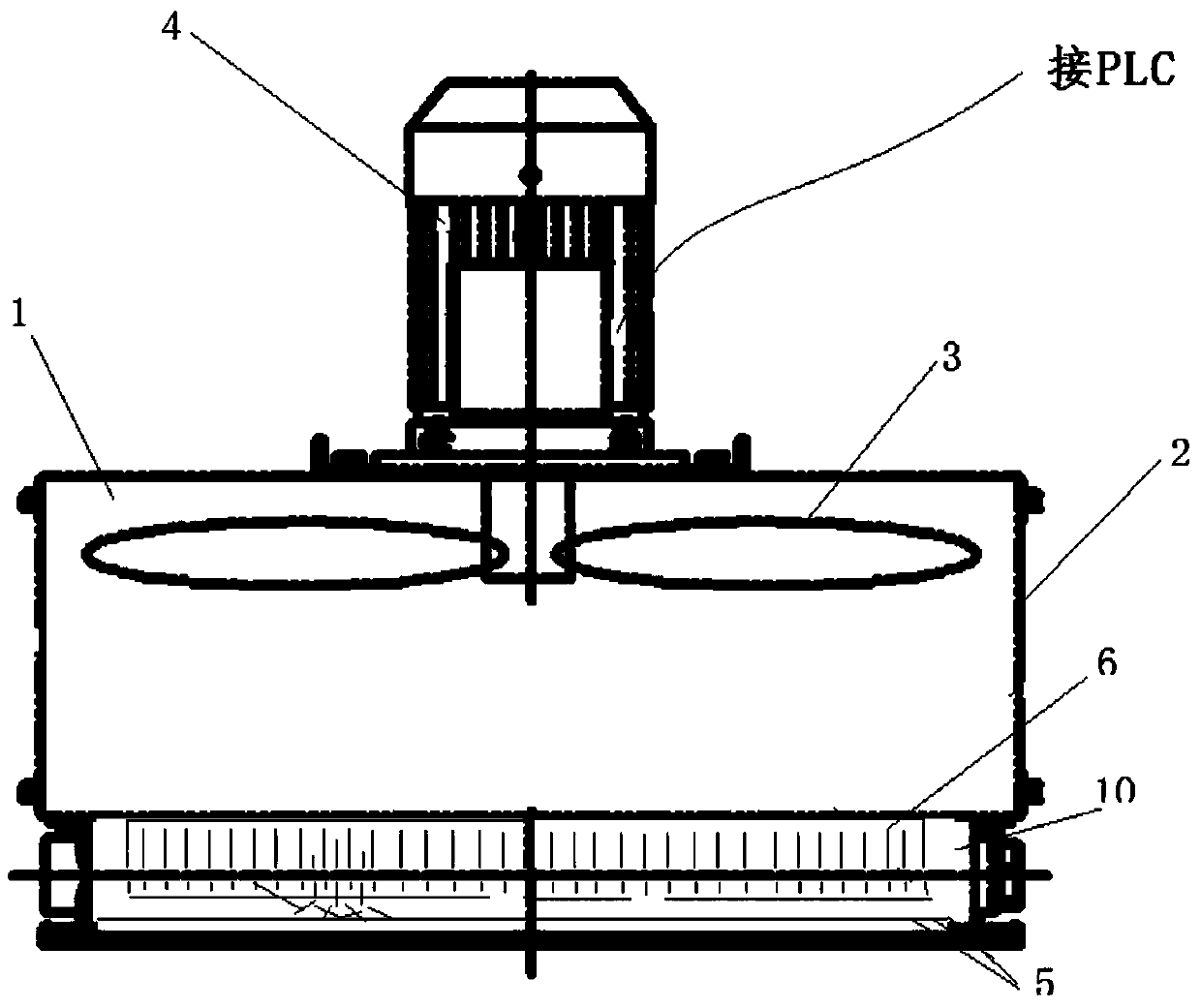
[0031] This embodiment is further elaborated on the basis of the embodiment of the suction air cooler. When the dust removal system receives the dust removal command, the motor that controls the cooling fan will operate at the set time t 0 = Within 600s, operate in the following operation mode to realize the resonance dust removal of the filter device:
[0032] 1) Reverse high speed: at the set high speed value n 1 The first setting time of reverse rotation is t 1 , the high-speed value n 1 In order to meet the heat dissipation requirements of the cooler, the lower limit of the fan speed, t 1 = 300s;
[0033] 2) Reverse low speed: at the set first low speed value n 2 Reverse rotation for the second set duration t 2 , 10s≤t 2 ≤60s, the first low speed value n 2 is the start-up speed value of the fan, t 2 = 30s;
[0034] 3) Forward rotation: with the set forward rotation value n 3 Forward rotation third set duration t 3 , the forward rotation value n 3 is the start-...
Embodiment 2
[0038] This embodiment is further elaborated on the basis of the embodiment of the suction air cooler. When the dust removal system receives the dust removal command, the motor that controls the cooling fan will operate at the set time t 0 = Within 360s, operate in the following operation mode to realize the resonance dust removal of the filter device, see Figure 5 :
[0039] 1) Reverse high speed: at the set high speed value n 1 The first setting time of reverse rotation is t 1 , the high-speed value n 1 In order to meet the heat dissipation requirements of the cooler, the lower limit of the fan speed, t 1 = 60s;
[0040] 2) Reverse low speed: at the set first low speed value n 2 Reverse rotation for the second set duration t 2 , the first low speed value n 2 is the start-up speed value of the fan, t 2 = 10s;
[0041] 3) Forward rotation: with the set forward rotation value n 3 Forward rotation third set duration t 3 , the forward rotation value n 3 In order to ...
Embodiment 3
[0045] This embodiment is further elaborated on the basis of the embodiment of the suction air cooler. When the dust removal system receives the dust removal command, the motor that controls the cooling fan will operate at the set time t 0 = Within 960s, operate in the following operation mode to realize the resonance dust removal of the filter device:
[0046] 1) Reverse high speed: at the set high speed value n 1 The first setting time of reverse rotation is t 1 , the high-speed value n 1 In order to meet the heat dissipation requirements of the cooler, the lower limit of the fan speed, t 1 = 600s;
[0047] 2) Reverse low speed: at the set first low speed value n 2 Reverse rotation for the second set duration t 2 , the first low speed value n 2 is the start-up speed value of the fan, t 2 = 60s;
[0048] 3) Forward rotation: with the set forward rotation value n 3 Forward rotation third set duration t 3 , the forward rotation value n 3 is the start-up speed value ...
PUM
 Abstract
Description
Claims
Application Information
 - R&D
- Intellectual Property
- Life Sciences
- Materials
- Tech Scout
- Unparalleled Data Quality
- Higher Quality Content
- 60% Fewer Hallucinations
Browse by: Latest US Patents, China's latest patents, Technical Efficacy Thesaurus, Application Domain, Technology Topic, Popular Technical Reports.
© 2025 PatSnap. All rights reserved.Legal|Privacy policy|Modern Slavery Act Transparency Statement|Sitemap|About US| Contact US: help@patsnap.com


