Electric power system static state estimation method considering PMU branch current phasor

A power system and static state technology, applied in the direction of calculation, instrumentation, data processing applications, etc., can solve the problems of small Jacobian proof elements, failure to use PMU, loss of meaning, etc., to achieve good estimation accuracy, good estimation stability, Estimate the effect of high precision

Inactive Publication Date: 2017-09-15
宁波飞拓电器有限公司
View PDF3 Cites 5 Cited by
  • Summary
  • Abstract
  • Description
  • Claims
  • Application Information

AI Technical Summary

Problems solved by technology

The PMU measurement can directly measure the node voltage and phase angle. Once all the nodes of the power grid are equipped with PMUs, the problem of state estimation will be greatly simplified, and the state estimation based on SCADA will lose its meaning.
[0004] The current state estimation model using PMU measurement generally either only uses PMU measurement for linear estimation, or adds PMU voltage amplitude and phase angle measurement on the basis of SCADA measurement for nonlinear estimation. The former is in the current PMU unobservable configuration. Difficult to do in the case of the latter without the use of PMU branch current phasor measurements
Branch current amplitude measurement is rarely used in transmission network state estimation for the following reasons: ① Current amplitude measurement is not easy to decouple active and reactive power; ② Current amplitude measurement cannot provide direction information, which will lead to multiple solutions ③When the line susceptance is small, using the current amplitude measurement to form the Jacobian matrix may cause numerical problems due to the small corresponding Jacobian proof elements
In short, it is inconvenient to directly use the current amplitude measurement in the state estimation of the transmission network, and the phase angle measurement of the branch current cannot be directly used

Method used


Image

  • Electric power system static state estimation method considering PMU branch current phasor
  • Electric power system static state estimation method considering PMU branch current phasor
  • Electric power system static state estimation method considering PMU branch current phasor

Examples


Embodiment Construction

[0035] Below in conjunction with accompanying drawing, the present invention is described in further detail:

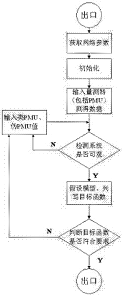
[0036] combine figure 1 , figure 2 As shown, the static state estimation method of the power system that introduces the PMU branch current phasor is as follows:

[0037] Enter the known data in the network, including the status of the connection information.

[0038] Initialize the system to prepare for a new state estimation.

[0039] Input the quantity measurement measured in the SCADA system, and input the data measured by the PMU device into the system at the same time, so that the data of the SCADA system and the data of the PMU are mixed.

[0040] According to the number and location of PMU configurations, it is judged whether the system is considerable, and if so, the assumption of the model is made and the objective function is listed.

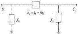
[0041] In the above system, the parameters of the system branch, the network connection and the measurement system are ...


PUM


Abstract

The invention discloses an electric power system static state estimation method considering PMU branch current phasor. The method is characterized by, to begin with, listing measurement equations according to known data in a system; then, configuring a PMU device to the system according to a requirement for enabling the system to reach observability after calculation; and applying the data obtained by the PMU to the system. The method, mainly based on the PMU data and supplemented by supplement of SCADA data and PMU pseudo-measurement data obtained after measurement transformation as well as PMU-similar data to data of a PMU observability insufficient point, enables the system reach observability, so that the estimation precision of the system is improved. The method can obtain accurate data under the condition of configuring less PMU data, and by making full use of the PMU measurement data, can carry out state estimation better.

Description

technical field [0001] The invention relates to a state estimation method in a power system, in particular to a static state estimation method of a power system introducing a PMU branch current phasor. Background technique [0002] With the continuous expansion of the grid scale and the increasingly complex network structure in the power system, the automation level of the power system dispatch center also needs to be gradually developed to a higher level, and the Energy Management System (EMS) has been widely used. Among them, the state estimation is the core functional module of the energy management system. Based on the structure, parameters and real-time measurement of the power grid, it provides a reliable and complete real-time database of the power system for other advanced application software. Foundation. [0003] Before the measurement technology of the Phasor Measurement Unit (PMU) based on the Global Positioning System (Global Positioning System, GPS) was applie...

Claims


Application Information

Patent Timeline
Patent Type & Authority Applications(China)
IPC IPC(8): G06Q50/06
Inventor 杜明葛泉波高仙管冰蕾
Owner 宁波飞拓电器有限公司
Why Eureka
Try Eureka