Banknote processing part and teller machine

A banknote processing and banknote technology, which is applied in the field of self-service financial equipment, can solve the problems of increased structure of the banknote processing unit, large parts, etc., and achieve the effect of compact structure

Active Publication Date: 2017-09-15
SHENZHEN YIHUA COMP +2
View PDF8 Cites 3 Cited by
  • Summary
  • Abstract
  • Description
  • Claims
  • Application Information

AI Technical Summary

Problems solved by technology

[0004] The object of the present invention is to provide a banknote processing unit and an ATM to solve the problem in the prior art that the components used to prevent foreign matter from entering the banknote access unit from the gap between the top of the housing and the banknote guide plate are relatively large in volume. Large, resulting in a technical problem of increasing the structure of the entire banknote processing department

Method used


Image

  • Banknote processing part and teller machine
  • Banknote processing part and teller machine
  • Banknote processing part and teller machine

Examples


Embodiment 1

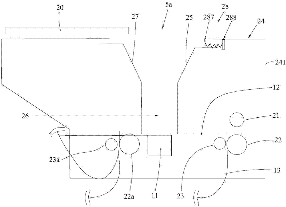
[0034] Please also refer to image 3 and Figure 4 , the banknote processing unit provided by the present invention will now be described. The banknote processing section includes a gate 20, a banknote access section 10 and a pick-up roller 21. The gate 20 is located at the banknote deposit and withdrawal opening 5a. For the banknotes put in, the pickup roller 21 is used to output the banknotes in the banknote depositing and withdrawing unit 10 to the transport path 13 . Specifically, the banknote access portion 10 includes a housing 24, a banknote access opening 5a, a banknote pressing plate 27, and a banknote guide plate 25. The housing 24 is a box-shaped structure with a top and surrounding side walls. 5a is set on the top of the housing 24, the gate 20 is a sliding shutter located at the banknote access opening 5a, and the banknote guide plate 25 is located inside the housing 24 and can move below the banknote access opening 5a and at the bottom of the housing 24. The f...

Embodiment 2

[0046] The technical features of the banknote processing unit in this embodiment are basically the same as those in Embodiment 1, the difference is that in this embodiment, please refer to Figure 6 The above-mentioned first connection part 281 , telescopic part 282 and second connection part 283 are an integral structure made of elastic material, that is, the entire sealing member 28 has elasticity, and the elastic material is preferably foam or rubber or sponge.

[0047] In addition, in this embodiment, the height of the telescopic portion 282 and the height of the first connecting portion 281 are both smaller than the height of the second connecting portion 283, and the height of the second connecting portion 283 is from the inner wall of the top of the casing 24 to the banknote guide. The height difference of the top surface of the plate 25 enables the seal 28 to ensure the gap between the top of the sealing housing 24 and the banknote guide plate 25, and also make the stru...

Embodiment 3

[0050] The technical features of the banknote processing unit in this embodiment are basically the same as those in Embodiment 1, the difference is that in this embodiment, please refer to Figure 7, the above-mentioned sealing element 28 is a telescoping structure, and the sealing element 28 includes several sequentially socketed elements that can be sequentially expanded and contracted. Specifically, in this embodiment, the above-mentioned sealing member 28 includes three sockets, which are respectively the first socket 284, the second socket 285 and the third socket 286, wherein the first socket 284 is fixedly connected to the banknote guide plate 25 , the third socket 286 is in contact with the top of the casing 24 , and the second socket 285 is connected between the first socket 284 and the third socket 286 . The first socket 284, the second socket 285 and the third socket 286 are elongated boxed structures, and the length and width of the first socket 284 are less than t...


PUM


Abstract

The invention provides a banknote processing part which comprises a banknote storing and withdrawing part. The banknote storing and withdrawing part comprises a housing, a banknote storing and withdrawing opening which is arranged at top of the housing, a banknote guiding board which is arranged in the housing and is movably arranged below the banknote storing and withdrawing opening and is between the banknote storing and withdrawing opening and the first sidewall of the housing. A clearance is arranged between the banknote guiding board and the top of the housing. The banknote storing and withdrawing part further comprises a telescopic sealing member for sealing the clearance. The sealing member comprises a first end which is fixedly connected with the banknote guiding board, and a second end which is in contacting connection with the top of the housing and can move to abut against the first sidewall so that the sealing member is compressed. The invention further provides a teller machine which comprises the banknote processing part. According to the banknote processing part, through setting the sealing member to the telescopic structure, occupation of an additional space of the banknote storing and withdrawing part by the sealing member is prevented, thereby promoting miniaturization of the teller machine.

Description

technical field [0001] The invention belongs to the technical field of self-service financial equipment, and more specifically relates to a banknote processing unit and an ATM. Background technique [0002] When the banknote processing section of the existing self-service financial equipment deposits banknotes, first, the gate is opened to open the banknote deposit and withdrawal opening of the banknote deposit and withdrawal section; The tight plate presses the input banknotes against the pick-up roller, and drives the pick-up roller to rotate to transport the banknotes to the banknote conveying channel. [0003] However, the banknote access section includes a housing and a banknote guide plate that is located inside the housing and can move between the lower side of the banknote access opening and the first side wall of the housing. The gap between the banknote guide plates enters and breaks down, and prevents the internal mechanism of the banknote access part from being ...

Claims


Application Information

Patent Timeline
Patent Type & Authority Applications(China)
IPC IPC(8): G07D11/00G07F19/00
CPCG07D11/16G07F19/20
Inventor 陈星
Owner SHENZHEN YIHUA COMP
Why Eureka
Try Eureka