Welding model and welding method of alloy steel turnout and trough type steel rail

A grooved rail and welding method technology, which is applied in welding equipment, aluminothermic welding equipment, metal processing equipment, etc., can solve the problems of tight supply cycle of trams, complicated welding joint forms, and heavy machining workload, etc. Achieve the effects of saving machining costs, small welding deformation, and reducing labor intensity

Pending Publication Date: 2017-09-19
CHINA RAILWAY BAOJI BRIDGE GRP
View PDF6 Cites 1 Cited by
  • Summary
  • Abstract
  • Description
  • Claims
  • Application Information

AI Technical Summary

Problems solved by technology

[0003] As a new type of green public transportation, modern trams have emerged in major cities. Based on the complex traffic situation in the city, turnouts are arranged in many places, especially in the bustling areas and stations in the city. The turnouts are in various forms and densely arranged. High-quality turnout structure, realizing the seamless welding of turnout and rail is a very critical link in the manufacture of modern trams; through the analysis of the butt joint structure of alloy steel turnout and rail, the selection of aluminothermic welding channel rail and Alloy steel turnout asymmetrical end face joint; channel rail and alloy steel turnout welding joint form is complex, if you want to use the existing technology, according to the aluminothermic welding of channel rail and channel rail butt joint, you need to weld the alloy steel turnout end The welding range is profiled according to the grooved steel rail. The machining workload is very large, which consumes a lot of cost and man-hours. It is difficult to meet the task of tight supply cycle and short delivery time for trams.

Method used


Image

  • Welding model and welding method of alloy steel turnout and trough type steel rail
  • Welding model and welding method of alloy steel turnout and trough type steel rail
  • Welding model and welding method of alloy steel turnout and trough type steel rail

Examples


Embodiment Construction

[0026] The present invention is described in detail below in conjunction with accompanying drawing;

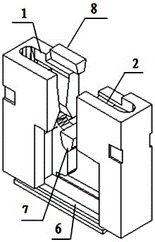
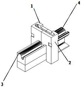
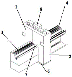
[0027] Such as figure 1 As shown, the present invention provides a welding model of an alloy steel turnout and a grooved steel rail, including a left sand mold 1 and a right sand mold 2 matched with the left sand mold 1, and the left sand mold 1 and the right sand mold 2 are fastened together It is installed on both sides of the joint 5 of the alloy steel turnout 3 and the grooved steel rail 4, and the bottom mold 6 is provided at the bottom of the left sand mold 1 and the right sand mold 2; the groove plug 7 is engaged in the joint 5 track groove, and the left sand mold After the mold 1 and the right sand mold 2 are fastened together, a diverter block 8 is arranged on the top injection port;

[0028] One side of the cavity after the fastening of the left sand mold 1 and the right sand mold 2 is a cuboid structure matching the structure of the alloy steel turnout 3, and the o...


PUM


Abstract

The invention discloses a welding model and welding method of an alloy steel turnout and a trough type steel rail. The welding model comprises a left sand mold and a right sand mold cooperating with the left sand mold. After being buckled, the left sand mold and the right sand mold are arranged on the two sides of a joint of the alloy steel turnout and the trough type steel rail. A bottom mold is arranged at the bottom of the left sand mold and the bottom of the right sand mold. The sand molds matched with the joint of the alloy steel turnout and the trough type steel rail, the bottom mold, a trough type plug block and a division block are arranged, and a closed thermit welding forming cavity is formed through cooperation between modules and manual filling and box sealing. The welding model cooperates with process methods and process parameters obtained through tests for the joint form, a casting system and the like for welding, a welding joint is stable in quality and good in performance, and various indexes meet the product performance requirement.

Description

technical field [0001] The invention relates to the technical steel structure connection field, in particular to a welding model and a welding method of an alloy steel turnout and a grooved steel rail. Background technique [0002] Thermite welding has the advantages of simple equipment, convenient use, cost-effectiveness, safety and reliability, and does not require external power supply. It is widely used in the welding of track seamless lines; Applied to the welding of grooved steel rails and grooved steel rails, with the same material and symmetrical end faces on both sides of the joint; [0003] As a new type of green public transportation, modern trams have emerged in major cities. Based on the complex traffic situation in the city, turnouts are arranged in many places, especially in the bustling areas and stations in the city. The turnouts are in various forms and densely arranged. High-quality turnout structure, realizing the seamless welding of turnout and rail is ...

Claims


Application Information

Patent Timeline
Patent Type & Authority Applications(China)
IPC IPC(8): B23K23/00
CPCB23K23/00
Inventor 王志翔薛宏强刘治国薛长利
Owner CHINA RAILWAY BAOJI BRIDGE GRP
Why Eureka
Try Eureka