
Method for kinematic calibration of six-degree-of-freedom robot based on monocular vision

A robot kinematics, monocular vision technology, applied in the direction of instruments, manipulators, program-controlled manipulators, etc., can solve the problems of measurement result fluctuation, radial distortion, result accuracy interference, etc., to improve the accuracy of distance measurement, improve the measurement accuracy The effect of distance accuracy and improved accuracy

Active Publication Date: 2017-09-19
TONGJI UNIV
View PDF8 Cites 15 Cited by
  • Summary
  • Abstract
  • Description
  • Claims
  • Application Information

AI Technical Summary

Problems solved by technology

[0005] 1. Robots often need a larger working space. In order to keep the target always within the field of view, this requires the camera to have a large field of view, and the corresponding size of each pixel is very large (difficult to control within 1mm 2 Within), it is difficult to accurately locate
[0006] 2. More targets will appear in the edge area of ​​the picture in the field of view
And this part has very serious radial distortion
Even after the camera is calibrated, the error it brings will cause large fluctuations in the measurement results, which will interfere with the accuracy of the results
[0007] In addition, the traditional methods of robot calibration mostly use the DH model to model the robot. This modeling method has a fundamental flaw, that is, when two axes are parallel or nearly parallel, the relative position error of the two axes Modeling does not conform to the small error model, which may cause large member offset errors
Moreover, most of the existing methods default to a translation relationship between the end of the robot and the camera, and the coordinate transformation between the two is relatively simple. For a six-degree-of-freedom robot, due to the high degree of freedom of the robot, this coordinate transformation method will cause large errors

Method used


Image

  • Method for kinematic calibration of six-degree-of-freedom robot based on monocular vision
  • Method for kinematic calibration of six-degree-of-freedom robot based on monocular vision
  • Method for kinematic calibration of six-degree-of-freedom robot based on monocular vision

Examples


Embodiment Construction

[0043] The present invention will be described in detail below in conjunction with the accompanying drawings and specific embodiments. This embodiment is carried out on the premise of the technical solution of the present invention, and detailed implementation and specific operation process are given, but the protection scope of the present invention is not limited to the following embodiments.

[0044]A common step in robot calibration is to construct a kinematic model based on the structural characteristics of the robot. And use the model characteristics to establish the constraint relationship between the observed variable and the variable to be calibrated; through the external sensor, the required observed variable is measured with high precision; using the constraint relationship and multiple sets of measured values, through the relevant mathematical optimization method, the optimization of the variable to be calibrated is realized; In this way, the mechanical parameters ...


PUM


Abstract

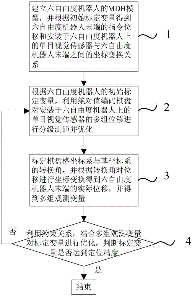
The invention relates to a method for kinematic calibration of a six-degree-of-freedom robot based on monocular vision. The method comprises the steps that an MDH model of the six-degree-of-freedom robot is built, and instruction displacement of the tail end of the six-degree-of-freedom robot and the coordinate transformation relation (please see the formula in specifications) between a monocular vision sensor installed on the six-degree-of-freedom robot and the tail end of the six-degree-of-freedom robot are obtained according to an initial calibration variable U; according to the initial calibration variable U of the six-degree-of-freedom robot, grading ranging and optimizing are conducted on multiple sets of displacement delta' of the monocular vision sensor installed on the six-degree-of-freedom robot through an absolute value coding checkerboard; actual displacement delta of the tail end of the six-degree-of-freedom robot is obtained, and multiple sets of observed variables Vk are obtained; and the constraint relation is used, the multiple sets of observed variables Vk are combined to optimize the calibration variable U, whether the calibration variable U reaches positioning precision or not is judged, if yes, the kinematic calibration of the six-degree-of-freedom robot is completed, and otherwise, returning is conducted. Compared with the prior art, the method for the kinematic calibration of the six-degree-of-freedom robot based on the monocular vision has the advantages that ranging precision is high, practicability is high, and the cost is saved.

Description

technical field [0001] The invention relates to the field of industrial robot calibration, in particular to a monocular vision-based six-degree-of-freedom robot kinematics calibration method. Background technique [0002] Accurately measuring the displacement of the working end of the robot is the core of completing the robot calibration. Its pose is usually measured with the help of external sensors. Commonly used equipment includes precision measuring instruments such as three-coordinate measuring instruments and theodolites. However, the common disadvantages of these solutions are that the equipment is expensive (hundreds of thousands or even millions), and the use method is cumbersome and complicated. It often requires on-site calibration and manipulation by professionals, and the threshold for use is high; on the other hand, such equipment usually requires a large It is difficult to meet the requirements of the production site for high efficiency and convenience. [...

Claims


Application Information

Patent Timeline
IPC IPC(8): B25J9/16G06T7/73
CPCB25J9/1661B25J9/1697G06T7/75
Inventor 陈启军张奎韩新承陈玺王志峰周自强
Owner TONGJI UNIV
Learn More