Material mixing and transporting shaft and multi-material mixing and transporting device

A material mixing and conveying device technology, applied in the direction of packaging, etc., can solve the problems that the mixer is difficult to achieve the mixing effect, slagging, heat loss increase, etc., and achieve the effect of improving the effect of thermal mixing and conveying

Active Publication Date: 2017-09-19
CHNA ENERGY INVESTMENT CORP LTD +1
View PDF9 Cites 5 Cited by
  • Summary
  • Abstract
  • Description
  • Claims
  • Application Information

AI Technical Summary

Problems solved by technology

[0003] However, in the pyrolysis technology with solid heat carrier as the core, insufficient pyrolysis or local overheating often occurs due to uneven mixing of materials and heat carrier, especially for asphaltene-rich materials such as coal Direct liquefaction of residues, heavy asphalt, etc., local overheating will cause strong bonding, resulting in slagging and blockage of the delivery pipeline
[0004] For this reason, a spiral material mixing device has appeared in the prior art to realize the mixing of materials at room temperature. However, the effect of material mixing is largely limited by the length of the screw mixer. For example, mixing materials with a short stroke It is difficu

Method used


Image

  • Material mixing and transporting shaft and multi-material mixing and transporting device
  • Material mixing and transporting shaft and multi-material mixing and transporting device
  • Material mixing and transporting shaft and multi-material mixing and transporting device

Examples


Embodiment Construction

[0036] Specific embodiments of the present invention will be described in detail below in conjunction with the accompanying drawings. It should be understood that the specific embodiments described here are only used to illustrate and explain the present invention, and are not intended to limit the present invention.

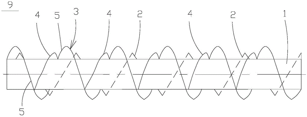
[0037] figure 1 shows the simplicity of the material mixing conveying shaft 9 of the present invention, as figure 1 As shown, the material mixing conveying shaft 9 includes a rotatable shaft body 1, for example, the shaft body 1 can be driven to rotate by a driving device such as a motor 6, wherein the shaft body 1 is provided with an inner shaft extending axially for pushing materials. The helical belt 2 and the outer helical belt 3 extending axially for feeding back, wherein the helical directions of the outer helical belt 3 and the inner helical belt 2 are opposite, and the inner edge of the outer helical belt 3 and the outer peripheral surface of the shaft bo...


PUM


Abstract

The invention relates to the field of material mixing transportation, and discloses a material mixing and transporting shaft and a corresponding multi-material mixing and transporting device. The material mixing and transporting shaft comprises a rotatable shaft body (1), an internal spiral band (2) and an external spiral band (3) are arranged on the shaft body (1), wherein the internal spiral band (2) extends in the axial direction to push materials, and the external spiral band (3) extends in the axial direction to return the materials; the external spiral band (3) and the internal spiral band (2) are opposite in spiral direction, and a gap exists between the internal side edge of the external spiral band (3) and the peripheral surface of the shaft body (1); and a material returning wing blade (4) is arranged on the external spiral band (3) with an included angle, the extending direction of the material returning wing blade (4) is consistent with the extending direction of the internal spiral band (2), and through the material pushing and lift material mixing functions of the material returning wing blade (4), the material mixing and transporting shaft can enhance the thermal mixing and transporting effect of the materials remarkably.

Description

technical field [0001] The invention relates to the technical field of material mixing and conveying, in particular to a material mixing and conveying shaft and a multi-material mixing and conveying device provided with the material mixing and conveying shaft. Background technique [0002] At present, with the increasingly serious environmental problems, efficient and clean utilization of biomass, organic-rich solid waste and low-rank coal is required. For this reason, medium and low temperature pyrolysis technology has played a significant role in cleaning the above substances. For example, after heat treatment of low-grade coal, on the one hand, high value-added coal tar can be obtained, and on the other hand, semi-coke (semi-coke) can be obtained after upgrading. Its composition and properties are close to bituminous coal, which can effectively prevent spontaneous combustion. , and is easy to transport and store, and can be widely used in power generation, gas production,...

Claims


Application Information

Patent Timeline
IPC IPC(8): B65G33/26B65G33/24B65G33/32
CPCB65G33/24B65G33/26B65G33/32
Inventor 陈爱国芦海云顾佥郭治郭屹
Owner CHNA ENERGY INVESTMENT CORP LTD
Why Eureka
Try Eureka