
Horizontal jet grouting drilling machine

A technology of horizontal rotary jetting and drilling rig, applied in drilling equipment, earthwork drilling, drilling equipment and methods, etc., can solve the problems of short life, large loss, poor stability, etc., achieve small equipment loss, meet construction requirements, guarantee The effect of construction speed and quality

Pending Publication Date: 2017-09-19
CHINA RAILWAY CONSTR HEAVY IND
View PDF6 Cites 4 Cited by
  • Summary
  • Abstract
  • Description
  • Claims
  • Application Information

AI Technical Summary

Problems solved by technology

[0005] The purpose of the present invention is to provide a horizontal rotary jet drilling machine, which can solve the problems of poor stability, large loss and short service life during use.

Method used


Image

  • Horizontal jet grouting drilling machine
  • Horizontal jet grouting drilling machine
  • Horizontal jet grouting drilling machine

Examples


Embodiment Construction

[0031] The core of the present invention is to provide a horizontal rotary grouting drilling rig, which can solve the problems of low construction efficiency, poor effect, and lack of ability to drive bolts during use.

[0032] In order to enable those skilled in the art to better understand the solution of the present invention, the present invention will be further described in detail below in conjunction with the accompanying drawings and specific embodiments.

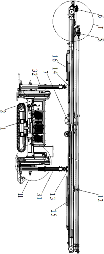
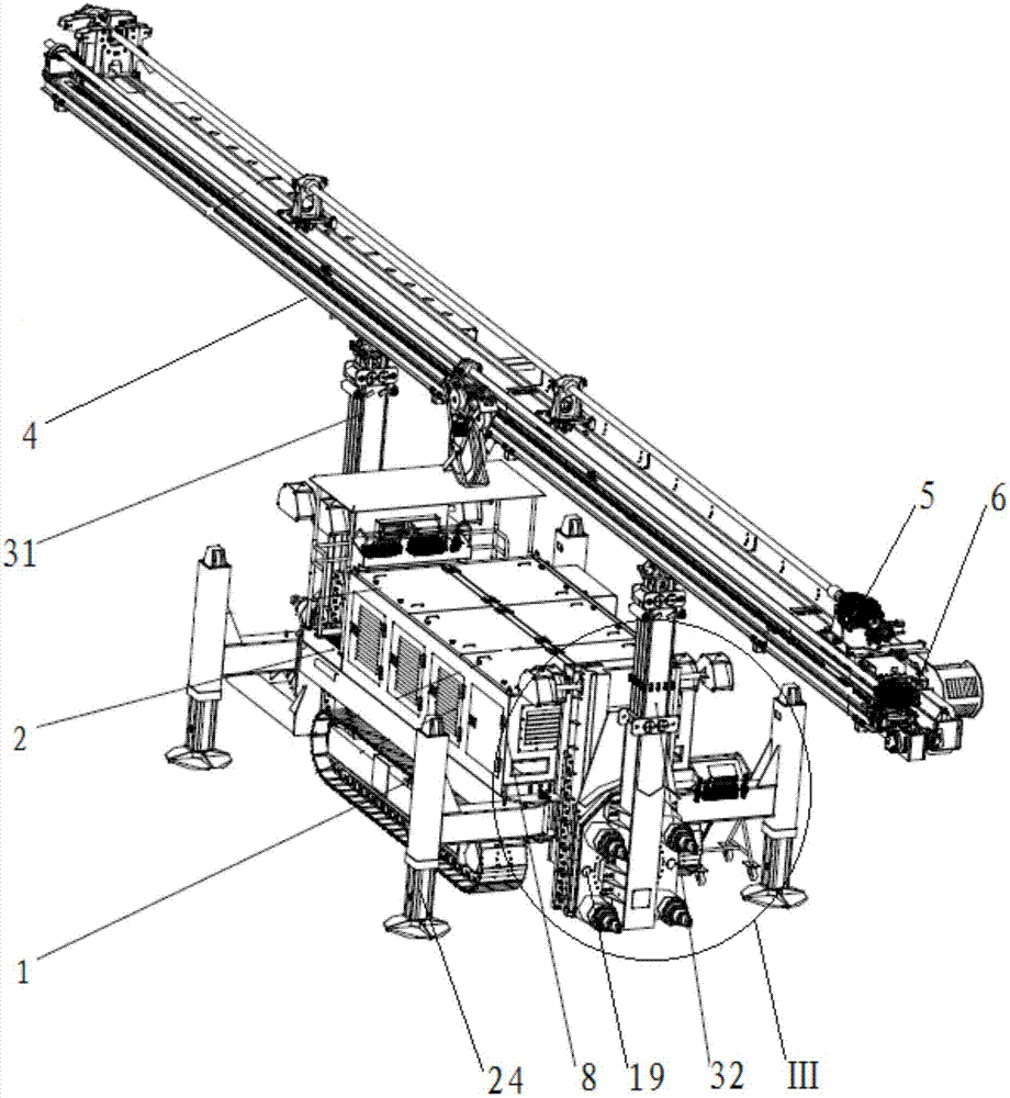
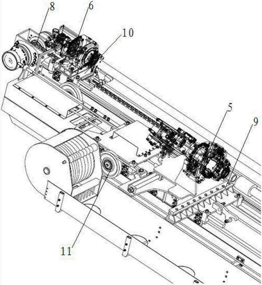
[0033] Please refer to Figure 1 to Figure 3 , figure 1 It is a structural schematic diagram of a specific embodiment of the horizontal jet drilling machine provided by the present invention; figure 2 It is another structural schematic diagram of a specific embodiment of the horizontal rotary jet drilling machine provided by the present invention; image 3 for figure 1 The enlarged schematic diagram of part I in the middle.

[0034] The horizontal jet jet drilling rig provided by the specific embodiment of the ...


PUM


Abstract

The invention discloses a horizontal jet grouting drilling machine which comprises a drilling machine platform and a lifting arm, wherein rotary working devices are arranged at the front end and rear end of the drilling machine platform; each of the rotary working devices comprises a fixing base, a rotating base, a gear motor and a rotary support with teeth on external circle and without tooth on internal circle; the fixing base is fixedly connected with the drilling machine platform; the rotating base is fixedly arranged at the bottom end of the lifting arm; the gear motor is arranged on the rotating base; the internal circle of the rotary support is fixedly connected with the rotating base; the external circle of the rotary support is fixedly connected with the fixing base; the external circle of the rotary support is meshed with the teeth of the gear motor; the gear motor is used for driving the rotating base and the lifting arm to swing so as to drive a cantilever crane to swing; front and rear dual rotary working devices are adopted for synchronously driving the cantilever crane to swing, so that sufficient power can be supplied to the machine for swinging under various working conditions, the rotating angle of the cantilever crane can be guaranteed, the machine can meet the construction requirement, the machine stability can be guaranteed, the machine loss is less, the construction quality is guaranteed and the construction safety is promoted.

Description

technical field [0001] The invention relates to the technical field of tunnel engineering machinery, in particular to a horizontal jet jet drilling machine. Background technique [0002] In the current tunnel engineering construction, there are various construction machinery products suitable for various construction methods, among which the horizontal rotary jet drilling machine is the most commonly used one. [0003] At present, most of the rotary excavation of tunnels adopts the rotary mode of the single-drive working device. Since the direction of the center of gravity of the horizontal rotary jet drilling rig deviates during side excavation, the stability decreases. In order to meet the requirements of rotary torque, pressing force, and speed, the rotary drive device It is easy to twist, jitter and stick. This single-drive rotary method not only limits the openness of the design of the working device, but also causes greater wear and tear and a short life cycle of the ...

Claims


Application Information

Patent Timeline
Patent Type & Authority Applications(China)
IPC IPC(8): E21B7/02E21B15/00
CPCE21B7/021E21B15/003
Inventor 刘飞香刘在政邹海炎杨宇澜吕展鹏张廷寿张海涛兰文军王旭赵俊朱斌聂四军
Owner CHINA RAILWAY CONSTR HEAVY IND
Learn More