Zero leakage hydraulic lock

A technology of hydraulic lock and zero leakage, applied in the field of hydraulic components, can solve the problems of inability to meet the use requirements, low reliability index, damage and other problems

Active Publication Date: 2017-09-19
BEIJING INST OF SPACE LAUNCH TECH +1
View PDF8 Cites 1 Cited by
  • Summary
  • Abstract
  • Description
  • Claims
  • Application Information

AI Technical Summary

Problems solved by technology

However, the reliability index of the hydraulic lock with the existing soft seal structure is low, generally 2000 times. When it is used for about 3000 times, the soft seal pad of non-metallic material will be damaged due to the jet flow phenomenon, which will cause the hydraulic lock to leak, which cannot be guaranteed. locking reliability
In the field of military and aerospace, the outrigger circuit of the projectile / arrow launch platform requires that the hydraulic lock should have a reliability index of 10,000 times, and the existing hydraulic lock with soft seal structure cannot meet its use requirements
Moreover, the hydraulic lock of the existing soft seal structure has the problem of poor manufacturability. Its structure has strict requirements on the compression amount of the soft seal, and multiple parts need to be prepared and paired with each other. There is no interchangeability, which is not conducive to mass production, and the cost higher

Method used


Image

  • Zero leakage hydraulic lock
  • Zero leakage hydraulic lock
  • Zero leakage hydraulic lock

Examples


Embodiment Construction

[0022] First of all, it needs to be explained that the orientation words such as front, back, left, right, up, and down in the present invention are only described according to the accompanying drawings, so as to be easy to understand, and are not intended to describe the technical solutions of the present invention and the scope of protection claimed. limit.

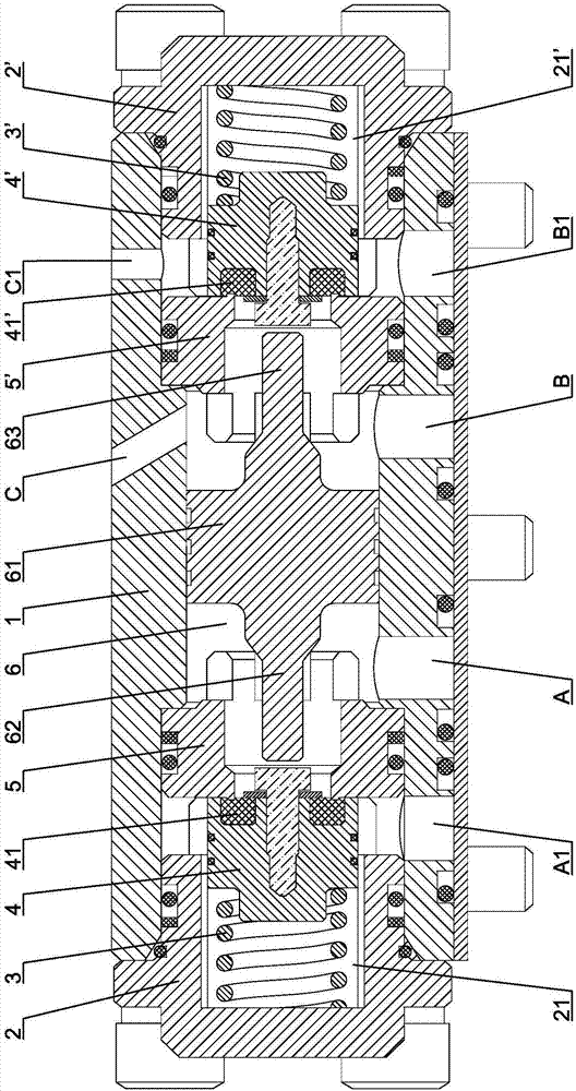
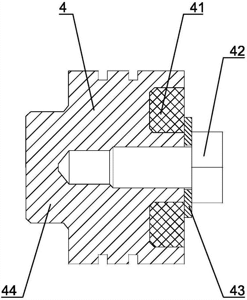
[0023] Such as Figure 1 to Figure 6Shown is a specific embodiment of a zero-leakage hydraulic lock of the present invention, including a cylindrical valve body 1 and a left end cover 2 and a right end cover 2' correspondingly fixed to the left and right ends of the valve body 1. Oil port A, oil port A1, oil port B and oil port B1 are respectively arranged on the valve body 1 . A first groove 21 is provided in the middle of the right end face of the left end cover 2, and a left spring 3 and a left valve 4 are arranged in the first groove 21 from left to right, and a first soft sealing ring 41 is embedded in the right e...


PUM


Abstract

The invention relates to a zero leakage hydraulic lock which comprises a valve body, a left end cover, a right end cover, a left spring, a left movable door, a left valve base, a right spring, a right moveable door, a right valve base and a sliding valve element, wherein an oil port A, an oil port A1, an oil port B and an oil port B1 are arranged on the valve body; a first soft sealing ring is arranged on the left movable door; a first penetrating hole and a first annular platform are arranged on the left valve base; the first annular platform is pressed on the first soft sealing ring; a second soft sealing ring is arranged on the right moveable door; a second penetrating hole and a second annular platform are arranged on the right valve base; the second annular platform is pressed on the second soft sealing ring; a left jacking rod of the sliding valve element is opposite to the left movable door; a right jacking rod of the sliding valve element is opposite to the right moveable door; the oil port A is communicated with the right end of the first penetrating hole; the oil port A1 is communicated with the left end of the first penetrating hole when the first soft sealing ring is separated from the first annular platform; the oil port B is communicated with the left end of the second penetrating hole; and the oil port B1 is communicated with the right end of the second penetrating hole when the second soft sealing ring is separated from the second annular platform. The zero leakage hydraulic lock has the advantages of excellent sealing property and high reliability.

Description

technical field [0001] The invention relates to a hydraulic component, in particular to a zero-leakage hydraulic lock using a soft seal. Background technique [0002] The hydraulic lock is the key component to realize the locking of the hydraulic system actuator at any position, and it is widely used in the locking circuit. Traditional hydraulic locks adopt hard sealing structures such as cone valves or ball valves, which are difficult to achieve zero leakage and cannot meet the requirements for long-term reliable locking. In order to solve the problems of traditional hydraulic locks, those skilled in the art have developed a hydraulic lock with a soft seal structure in order to achieve zero leakage and reliable locking. However, the reliability index of the hydraulic lock with the existing soft seal structure is low, generally 2000 times. When it is used for about 3000 times, the soft seal pad of non-metallic material will be damaged due to the jet flow phenomenon, which w...

Claims


Application Information

Patent Timeline
Patent Type & Authority Applications(China)
IPC IPC(8): F15B13/01
CPCF15B13/01
Inventor 陈建有刘薇郭小强郭建伟谢文建何寥
Owner BEIJING INST OF SPACE LAUNCH TECH
Why Eureka
Try Eureka