
Railway vehicle traction box with cooling system, method of application and railway vehicle

A technology for railway vehicles and traction boxes, which is applied in the field of traction boxes and electric traction vehicles, and can solve problems such as difficult cooling of electrical equipment

Active Publication Date: 2020-06-19
ALSTOM TRANSPORT TECH SAS
View PDF3 Cites 0 Cited by
  • Summary
  • Abstract
  • Description
  • Claims
  • Application Information

AI Technical Summary

Problems solved by technology

[0005] For high power traction boxes, it is difficult to adequately cool the room temperature of the components of electrical equipment by means of coolers such as air / air type heat exchangers

Method used


Image

  • Railway vehicle traction box with cooling system, method of application and railway vehicle
  • Railway vehicle traction box with cooling system, method of application and railway vehicle

Examples


Embodiment Construction

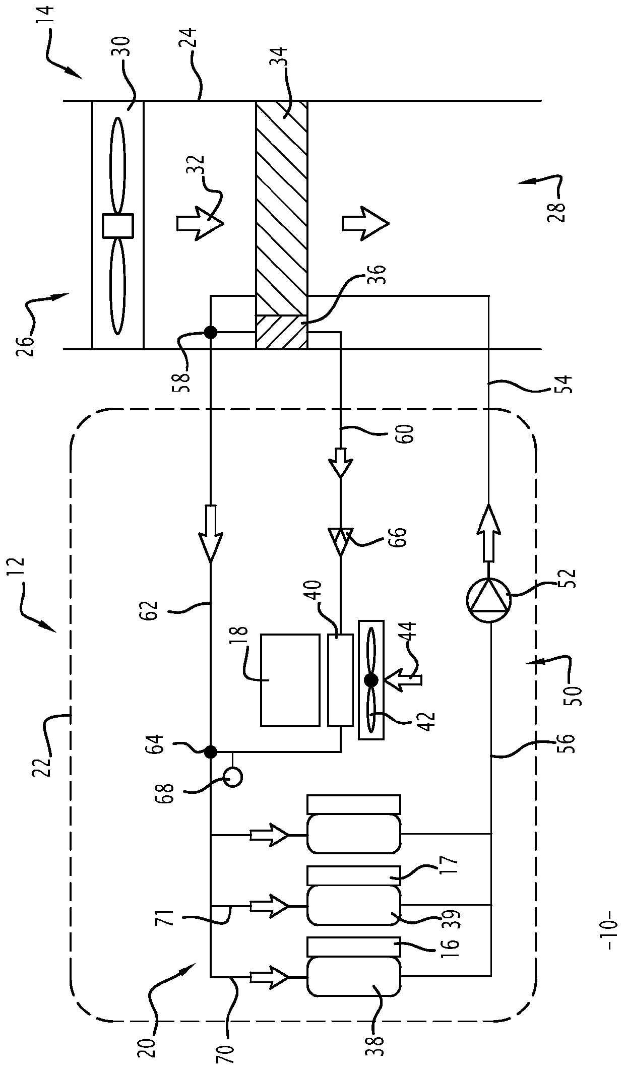
[0024] figure 1 A schematic front view of a traction box 10 of a railway vehicle according to an embodiment of the invention is shown.

[0025] The tank 10 includes a closed compartment 12 and a vent string 14 . The box 10 also comprises a first electrical equipment part 16 , 17 and a second electrical equipment part 18 arranged in the closed compartment 12 .

[0026] The box 10 further comprises cooling means 20 capable of removing the heat dissipated, in particular in the enclosed compartment 12 by said first 16 , 17 and second 18 parts of electrical equipment.

[0027] The cooling device 20 is arranged in the closed compartment 12 and in the ventilation string 14 .

[0028] Closed cabin 12 through the figure 1 Defined by the cover 22 shown in dotted line. Preferably, enclosure 22 is airtight. Thus, the air present inside said hood 22 is confined within the closed compartment 12 .

[0029] The second electrical equipment component 18 preferably includes elements for wh...


PUM


Abstract

A traction box of a railway vehicle includes pieces of electric equipment; and a cooling device including a first and second fluid circuits, respectively crossing first and second heat exchange areas with the pieces of electric equipment; and first and second of heat exchangers, respectively crossed by the first and the second fluid circuits and allowing heat exchange between the fluid and a first air flow. The fluid circuits include a first common conduit for fluid circulation, crossing the first exchanger, and then connected to the second and to a third parallel conduits, the second conduit belonging to the second fluid circuit and first crossing the second exchanger and then the second heat exchange area.

Description

technical field [0001] The invention relates to a traction box for a railway vehicle comprising a first piece of electrical equipment and a second piece of electrical equipment, and cooling means capable of removing the heat dissipated by said first piece of electrical equipment and the second piece of electrical equipment, said The cooling device comprises: a first fluid circuit and a second fluid circuit, the first fluid circuit and the second fluid circuit respectively pass through the heat exchange area with the first electrical equipment part and the second electrical equipment part, the first fluid circuit and the Each of the second fluid circuits forms a closed loop; and a first heat exchanger and a second heat exchanger, the first heat exchanger and the second heat exchanger are respectively connected by the first fluid circuit and the second A fluid circuit passes through and allows heat exchange between the fluid and the first gas stream. [0002] The invention is a...

Claims


Application Information

Patent Timeline
Patent Type & Authority Patents(China)
IPC IPC(8): H05K7/20
CPCH05K7/20263H05K7/20927H05K7/20909B60H1/00B61C11/00B61C3/00B61C17/00
Inventor 克里斯多夫·奥德马尔
Owner ALSTOM TRANSPORT TECH SAS
Learn More