Rotary airing sun-cure frame
A drying rack and turret technology, applied in the field of drying racks, can solve the problems of high energy consumption, poor effect of hot air drying paint, etc., and achieve the effect of low energy consumption
Inactive Publication Date: 2017-09-22
安徽枫帆轨道装备有限公司
View PDF3 Cites 2 Cited by
- Summary
- Abstract
- Description
- Claims
- Application Information
AI Technical Summary
Problems solved by technology
[0003] In view of the above-mentioned shortcomings of the prior art, the purpose of the present invention is to provide a rotary drying rack for solving the problems of poor hot air drying paint effect and large energy consumption in the prior art
Method used
View moreImage
Smart ImageViewing Examples
Examples
specific Embodiment approach
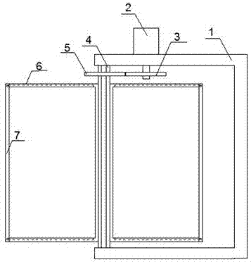
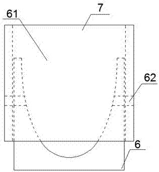
[0024] The specific embodiment: in the process of using, slide the door panel into the limit groove 61, then fix the limit rod 7, start the servo motor 2, the servo motor 2 drives the turret 4 to rotate, and the door panel is made by the rotation of the turret 4 Let the paint dry.
Login to View More PUM
 Abstract
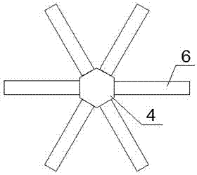
The invention discloses a rotary airing sun-cure frame. The rotary airing sun-cure frame comprises a rack, a servo motor, a first gear, a rotating frame body, a second gear, supporting frame bodies, limiting grooves, threaded holes and limiting rods; the servo motor is fixedly mounted on the upper plane of the rack; the first gear is fixedly mounted on an output shaft of the servo motor; the rotating frame body is rotatably mounted at the left end of the rack through a bearing; the second gear is fixedly mounted on the surface of the rotating frame body; the six supporting frame bodies are uniformly and fixedly mounted on the surface of the rotating frame body; the semi-elliptical limiting grooves are formed in the upper inner walls and the lower inner walls of the supporting frame bodies correspondingly; the side walls of the two ends of the limiting grooves are provided with the corresponding threaded holes; the limiting rods are also provided with the threaded holes corresponding to the threaded holes in the limiting grooves; and the limiting rods are fixed to the supporting frame bodies in the mode that bolts penetrate through the threaded holes. The rotary airing sun-cure frame has the advantages of being good in airing effect, small in energy consumption and the like.
Description
technical field [0001] The invention relates to a drying rack, in particular to a rotating drying rack. Background technique [0002] In the production process of high-speed iron door panels, it is usually necessary to spray paint on the door panels. After the painting is completed, the door panels need to be aired to dry the paint on the door panels quickly. Most of the drying devices on the market now use hot air drying. The drying method not only consumes a lot of energy but also has poor drying effect. Contents of the invention [0003] In view of the above-mentioned shortcomings of the prior art, the object of the present invention is to provide a rotary drying rack for solving the problems of poor hot air drying paint effect and high energy consumption in the prior art. [0004] In order to achieve the above purpose and other related purposes, the present invention discloses a rotary drying rack, comprising: a frame, a servo motor, a gear one, a turret, a gear two, ...
Claims
Login to View More Application Information
Patent Timeline
 Patent Type & Authority Applications(China)
IPC IPC(8): B05D3/04
CPCB05D3/0406
Inventor 王军
Owner 安徽枫帆轨道装备有限公司
Features
- R&D
- Intellectual Property
- Life Sciences
- Materials
- Tech Scout
- Unparalleled Data Quality
- Higher Quality Content
- 60% Fewer Hallucinations
Learn More Browse by: Latest US Patents, China's latest patents, Technical Efficacy Thesaurus, Application Domain, Technology Topic, Popular Technical Reports.
© 2025 PatSnap. All rights reserved.Legal|Privacy policy|Modern Slavery Act Transparency Statement|Sitemap|About US| Contact US: help@patsnap.com


