
Alloy wear-resistant screw

A screw and alloy technology, applied in the field of alloy wear-resistant screw, can solve the problem that the material in the barrel cannot be stirred, and achieve the effect of good injection molding effect, accelerated mixing and stirring, and high quality.

Inactive Publication Date: 2017-09-22
浙江贝美特机械有限公司
View PDF9 Cites 0 Cited by
  • Summary
  • Abstract
  • Description
  • Claims
  • Application Information

AI Technical Summary

Problems solved by technology

[0004] The problem to be solved by the present invention is that when the screw head of the screw in the prior art moves backward with the screw body away from the injection outlet of the barrel, the material at the front end of the barrel cannot be stirred

Method used


Image

  • Alloy wear-resistant screw
  • Alloy wear-resistant screw
  • Alloy wear-resistant screw

Examples


Embodiment Construction

[0018] The present invention will be further described below in conjunction with the accompanying drawings and embodiments.

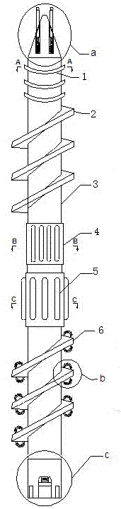
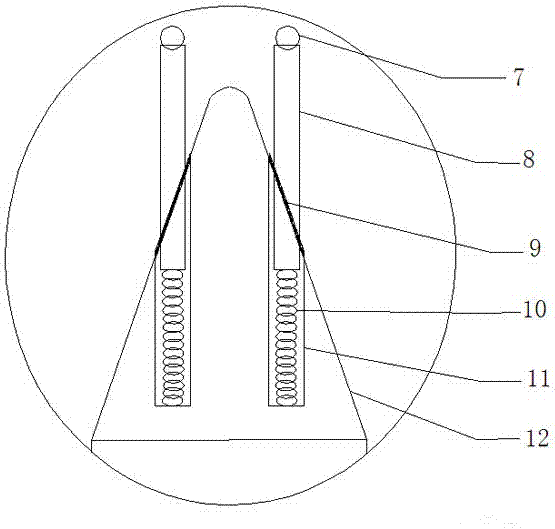
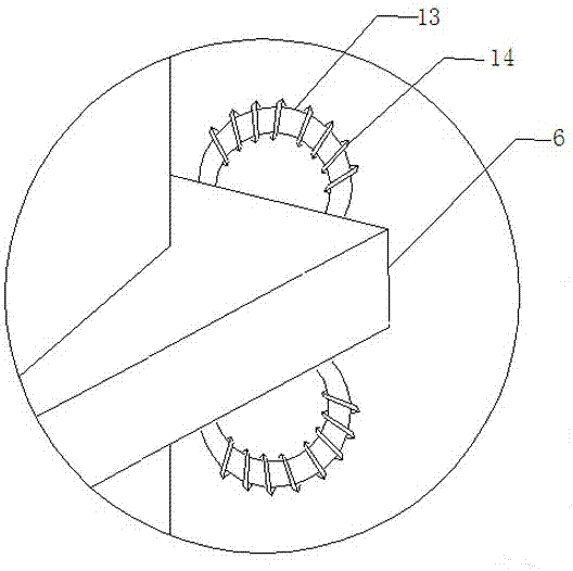
[0019] An alloy wear-resistant screw of the present invention comprises a first flight 1, a second flight 2, a screw body 3, a first mixing roller 4, a second mixing roller 5, a third flight 6, steel balls 7, Stirring rod 8, sealing ring 9, first spring 10, groove 11, screw head 12, stirring ring 13, fourth screw edge 14, second spring 15, push plate 16, screw tail part 17, keyway 18 and screw hole 19, the left and right sides of the screw head 12 are respectively provided with grooves 11, the first spring 10 is installed in the groove 11, the stirring rod 8 is installed on the first spring 10, and the front end of the stirring rod 8 protrudes outside the groove 11, stirring A steel ball 7 is installed on the upper end of the rod 8. During the mixing and mixing stage, the screw head 12 is located at the front end of the barrel, and the steel ball 7 is i...


PUM


Abstract

An alloy wear-resistant screw comprises first screw edges, second screw edges, a screw body, a first mixing roll, a second mixing roll, a third screw edge, a steel ball, stirring rods, sealing rings, first springs, a groove, a screw head, a stirring ring, a fourth screw edge, a second spring, a push plate, a screw tail, a key groove and screw holes. Each of the left side and right side in the screw head is provided with a groove. The first spring is mounted in each groove, the stirring rod is mounted on each first spring, the front ends of the stirring rods extend out of the corresponding grooves, and the sealing ring is mounted between an opening of each groove and the corresponding stirring rod. The screw head is mounted on the screw body. The alloy wear-resistant screw has the beneficial effects that when the screw head moves backwards along with the screw body and is away from an injection molding discharging opening of a material cylinder, materials at the front end of the material cylinder can still be stirred.

Description

technical field [0001] The invention relates to an alloy wear-resistant screw, which belongs to the technical field of screws. Background technique [0002] The outer surface of the screw is a cylinder with spiral grooves or a cone with a conical spiral groove. The screw is the core component of plastic molding equipment, the part that is heated, extruded and plasticized, and the core of plastic machinery. The screw head of the screw in the prior art will move backward along with the screw body away from the injection outlet of the barrel. In this process, because the screw head is far away from the injection outlet of the barrel, during the discharging process, the barrel The material at the front end cannot be stirred, so that the injection molding effect is not good, and it is easy to cause air bubbles in the product. In order to solve the above difficulties, it is necessary to develop an alloy wear-resistant screw that can still stir the material at the front end of the...

Claims


Application Information

Patent Timeline
Patent Type & Authority Applications(China)
IPC IPC(8): B29C45/60
CPCB29C45/60
Inventor 刘金琪
Owner 浙江贝美特机械有限公司
Features
  • Generate Ideas
  • Intellectual Property
  • Life Sciences
  • Materials
  • Tech Scout
  • Unparalleled Data Quality
  • Higher Quality Content
  • 60% Fewer Hallucinations
Learn More