
Snakelike mechanism guide rail

A guide rail and snaking technology, which is applied to conveyors, mechanical conveyors, transportation and packaging, etc., can solve the problems of undurable conveyor belts, small turning angle range, high cost of use, etc., to meet the requirements of fast picking work, reasonable structural design, The effect of reducing production costs

Pending Publication Date: 2017-09-22
侯孝琪
View PDF7 Cites 0 Cited by
  • Summary
  • Abstract
  • Description
  • Claims
  • Application Information

AI Technical Summary

Problems solved by technology

[0002] When picking tea leaves in mountainous tea gardens, the early picking method was purely manual, which was time-consuming, labor-intensive, and low in safety. With the rapid development of modern machinery and equipment, there are mechanical automatic picking equipment, but this equipment does not change the standard transmission of the original mechanical working machine. In the case of gears, it can only move in a straight line along the standard tooth guide rail in the same vertical plane. In fact, the tea trees in mountainous areas are not arranged in a straight line, and there are bending and displacement in the picking route. The traditional method is to use multi-section linear guide rails to splice. Unloading the machinery and re-running on the track, the use process is complicated, and the humanization is low. Of course, there are also transmission belts to realize small-angle turns, but the range of turning angles is small, and the conveyor belts are not durable, and the cost of use is high. Therefore, snakes need to be provided. Mechanism guide rail, without changing the standard transmission gear of the original mechanical working machine, realizes the displacement of the machine according to the horizontal bending direction of the guide rail during operation, meets the requirements of fast picking work, improves production efficiency, and reduces production costs

Method used


Image

  • Snakelike mechanism guide rail
  • Snakelike mechanism guide rail
  • Snakelike mechanism guide rail

Examples


Embodiment Construction

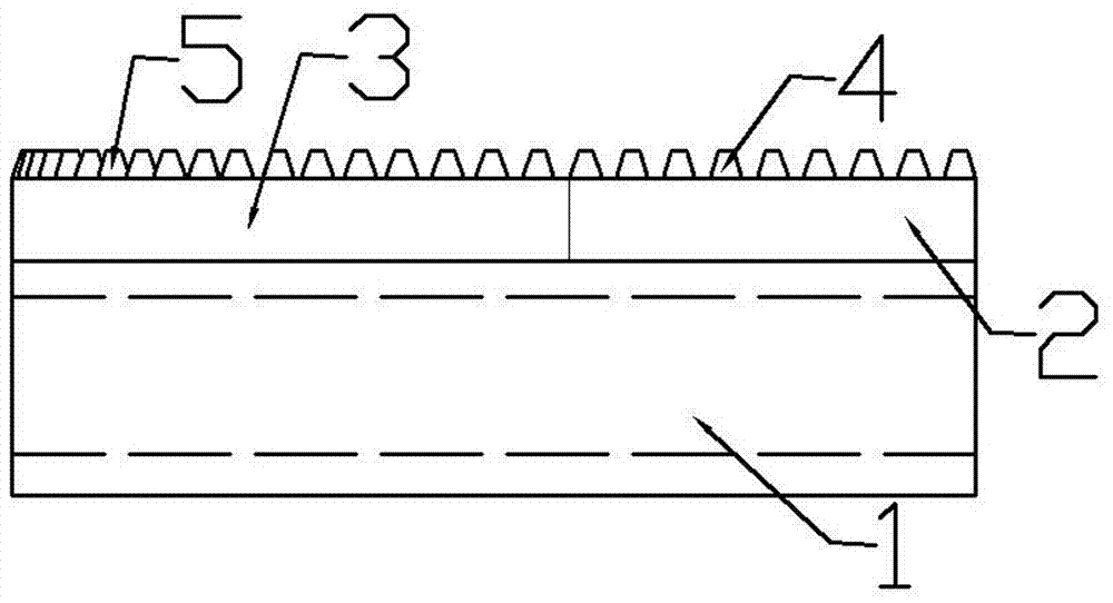
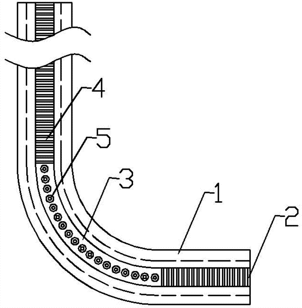
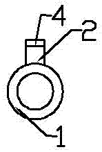
[0017] The snake guide rail provided by the present invention includes a track and teeth on the track. The track is erected on a cylindrical pipe 1. The pipe 1 is cylindrical, which can ensure that the mechanical equipment on it performs linear contact motion with it, rather than surface contact. Reduce friction and save energy; the track sections are set to straight track 2 and curved track 3. The teeth match the standard transmission gears of the working mother machine, including standard teeth 4 and special-shaped teeth 5. The standard teeth 4 are located on the straight track 2, which is conventional The standard rack section is convenient for the straight running of the standard working machine; the special-shaped tooth 5 is located on the center line of the curved track 3, and the special-shaped tooth 5 is in the shape of a truncated cone. The tooth pitch is equal to the tooth pitch of the standard tooth 4, and the tooth height of the profiled tooth 5 is equal to the tooth...


PUM


Abstract

The invention discloses a snakelike mechanism guide rail which comprises a rail and teeth positioned on the rail, wherein the rail is erected on a cylindrical pipeline, and segmented into a straight rail body and a bent rail body; the teeth are matched with a machine tool standard transmission gear, and comprise standard teeth and irregular teeth; the standard teeth are positioned on the straight rail body; the irregular teeth are positioned in the center line of the bent rail body; and each irregular tooth takes the shape of a cone frustum. The snakelike mechanism guide rail disclosed by the invention is reasonable in structural design and outstanding in using effect. Under the circumstance that the machine tool standard transmission gear of an original machine is unchanged, the irregular teeth matched with the machine tool standard transmission gear are adopted by the bent rail body of the snakelike mechanism guide rail, so that the position of the machine can be automatically changed in a running process according to the horizontal bending direction of the snakelike mechanism guide rail, the work demand for rapid picking can be met, the production efficiency can be improved, the production cost can be reduced, and the extensive meaning of popularization can be achieved.

Description

Technical field [0001] The present invention belongs to the technical field of mechanical equipment, and specifically relates to a snake guide rail. Background technique [0002] When picking tea in mountainous tea gardens, early manual picking was used, which was time-consuming and labor-intensive and low in safety. With the rapid development of modern machinery and equipment, there are mechanical automated picking equipment, but this equipment does not change the standard transmission of the original mechanical working machine. In the case of gears, they can only move in a straight line along the standard tooth guide in the same vertical plane. In fact, the tea trees in mountainous areas are not arranged in a straight line, and the picking route is bent and displaced. The traditional method is to use multi-section linear guides to splice. Unloading the machine to run on orbit again, the use process is complicated, and the user-friendliness is low. Of course, transmission belt t...

Claims


Application Information

Patent Timeline
IPC IPC(8): B65G35/00
CPCB65G35/00
Inventor 侯孝琪侯仁人
Owner 侯孝琪
Learn More