Ground anchor device suitable for saturated sandy soil site

A ground anchor and site technology, applied in construction, sheet pile wall, foundation structure engineering, etc., can solve the problems of liquefaction, insufficient uplift resistance, unable to solve the problem of soil liquefaction, etc., so as to reduce the loss of uplift force and ensure the uplift resistance. performance, the effect of improving the pullout resistance

Active Publication Date: 2017-09-22
宁波市交通建设工程试验检测中心有限公司
View PDF7 Cites 3 Cited by
  • Summary
  • Abstract
  • Description
  • Claims
  • Application Information

AI Technical Summary

Problems solved by technology

However, these ground anchor structures commonly used in soft soil formations cannot solve the problem of soil liquefaction caused by ground anchor drill pipe disturbance in saturated sandy soil formations
Therefore, it is necessary to improve the existing technology in order to fully solve various problems faced by ground anchor devices in saturated sandy soil sites, such as saturated sandy soil liquefaction, insufficient pull-out performance, etc.

Method used


Image

  • Ground anchor device suitable for saturated sandy soil site
  • Ground anchor device suitable for saturated sandy soil site
  • Ground anchor device suitable for saturated sandy soil site

Examples


Embodiment 1

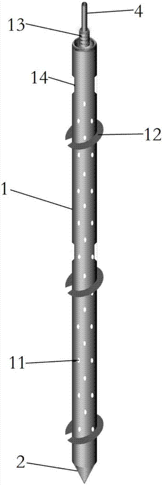
[0033] like figure 1 As shown, a ground anchor device suitable for saturated sandy soil sites includes a drill pipe 1 and a drill bit 2 . The main body of the drill pipe 1 is a hollow cylindrical tube, and a drill bit 2 is installed at the bottom end.

[0034] A plurality of water permeable holes 11 are evenly arranged on the outer wall of the drill pipe 1, and the excess pore water caused by the disturbance during the drilling of the drill pipe 1 into the saturated sandy soil can penetrate into the drill pipe 1 through the water permeable holes 11, so as to accelerate the vibration of the drill pipe 1 in the process of entering the soil The resulting excess pore water pressure dissipates, reducing the possibility of liquefaction, thereby ensuring the pullout resistance of the ground anchor drill pipe.

[0035] There are three-stage threaded disks 12 on the outer wall of the drill pipe 1. The diameter of the threaded disks 12 increases step by step along the drill pipe 1. Thi...

Embodiment 2

[0038] In this embodiment, on the basis of the above embodiments, the drill pipe 1 has a length of 150 cm and an outer diameter of 3.4 cm. The water permeable holes 11 are arranged in a rhombus or quincunx shape, with a hole spacing of 2-6 cm and a hole diameter of 0.1-0.2 cm. The location and diameter of the permeable holes 11 are calculated to ensure that the excess pore water enters the drill pipe 1 and reduce the possibility of liquefaction.

[0039] The disc diameter of the threaded disk 12 is 6-10 cm, and the single large-diameter threaded disk of the traditional ground anchor is replaced by the multi-stage small-diameter threaded disk 12, which can minimize the drill pipe 1 during the process of entering the soil. 1 The range of disturbed soil around.

[0040] The outer wall of the drill pipe 1 is provided with multi-stage rotating clamping grooves 14, and the distance between the rotating clamping grooves 14 of each stage is the same, and the position of the rotating ...

Embodiment 3

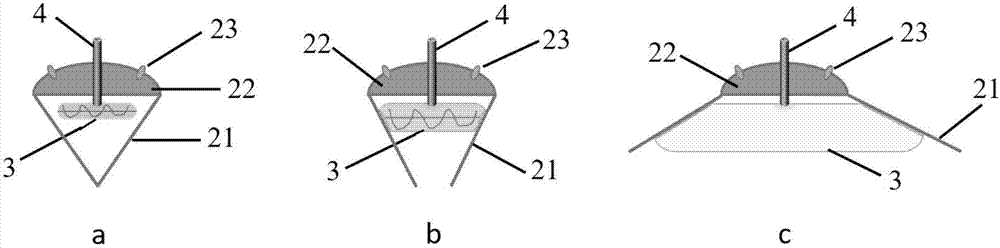
[0042] This embodiment is based on the foregoing embodiments, such as figure 2 As shown, the drill bit 2 includes a base 22 and a plurality of flaps 21 . The valve 21 is connected with the base 22 through a rotating shaft, and a torsion spring is installed in the rotating shaft, the valve 21 can be opened under force, and after the external force is removed, the valve 21 is closed under the spring force. The base 22 of the drill bit 2 is provided with a shaft lock 23 for controlling the opening angle of the valve 21 , and the position of the valve 21 is limited by the shaft lock 23 when the valve 21 is opened to a maximum angle. A water injection film bag 3 is installed in the cavity formed between each valve 21, and the water injection film bag 3 is connected with the water injection pipe 4 penetrating through the drill pipe 1. The water injection film bag 3 is ellipsoidal, and its horizontal length is much larger than the vertical length. Swells when water is injected.

...


PUM


Abstract

The invention discloses a ground anchor device suitable for a saturated sandy soil site. The ground anchor device comprises a drill rod and a drill bit. The drill bit is installed at the bottom end of the drill rod, and a plurality of water permeable holes are evenly distributed on the wall of the drill rod. The ground anchor device aims at reducing and solving the problem that in the process that a traditional ground anchor device drills into the saturated sandy soil site, overlarge disturbance is generated, and therefore, wide-range liquidation occurs to sandy soil around a ground anchor as much as possible. The water permeable holes are formed in the outer side of the drill rod. In the drill rod in-soil process, excess pore water caused by disturbance can permeate into the drill rod through the water permeable holes so that dissipating of the excess pore water is accelerated, therefore, the liquidation occurring possibility is reduced, and the pulling-resistant property of the ground anchor drill rod is ensured.

Description

technical field [0001] The invention relates to the field of civil traffic engineering equipment, in particular to a ground anchor device suitable for saturated sandy soil sites. Background technique [0002] When exploring or carrying out tests on loose and saturated sandy soil sites, the drilling of ground anchor reaction structures is often involved. In traditional soft ground, the spiral ground anchor structure is widely used because of its simple structure. Common manual spiral ground anchors (such as equipped with mechanical static penetrometers) usually have a drill disc diameter of more than 25cm, and are set as a single-piece spiral disc. The drill pipe is mostly made of solid steel anchor rod, which is heavy. [0003] When the static penetrating test and the borehole soil test were carried out in the loose and saturated sandy soil site, it was found that the resistance of the soil to the drill pipe was significantly weakened in the later stage of the above-mention...

Claims


Application Information

Patent Timeline
Patent Type & Authority Applications(China)
IPC IPC(8): E02D5/80
CPCE02D5/801E02D5/803E02D2250/0038E02D2600/30
Inventor 王维国干啸洪方继伟顾俊钢谢玲儿朱建朝陈立平官华李宗泉
Owner 宁波市交通建设工程试验检测中心有限公司
Why Eureka
Try Eureka