Grouting-free soil nailing device suitable for temporary support of side slope and construction method of grouting-free soil nailing device

A temporary support and side slope technology, applied in excavation, foundation structure engineering, sheet pile walls, etc., can solve the problems of increasing construction speed and saving engineering cost, low friction between surrounding soil bodies, complex procedures, etc., and achieves an improvement Pull-out bearing capacity, ensure pull-out performance, save the effect of complicated procedures

Pending Publication Date: 2022-04-12
CHONGQING JIAOTONG UNIVERSITY
View PDF3 Cites 0 Cited by
  • Summary
  • Abstract
  • Description
  • Claims
  • Application Information

AI Technical Summary

Problems solved by technology

The grouting type soil nailing refers to that the cone of the reinforced rod is directly driven into the soil, and the cement slurry is pressed to form a soil nail. It has the advantage of directly driving the nail and has a high pull-out resistance, and is suitable for holes that are difficult to form. Temporary slope engineering in soft soil layers such as silt and muddy soil, but the cost is higher than that of direct driving soil nails
[0004] However, at present, in temporary slope, foundation pit support and other projects, the drilling and grouting type and the grouting type soil nails are mostly used, and the direct drivin

Method used


Image

  • Grouting-free soil nailing device suitable for temporary support of side slope and construction method of grouting-free soil nailing device
  • Grouting-free soil nailing device suitable for temporary support of side slope and construction method of grouting-free soil nailing device
  • Grouting-free soil nailing device suitable for temporary support of side slope and construction method of grouting-free soil nailing device

Examples


Embodiment 1

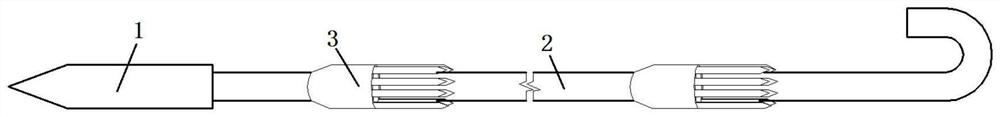
[0035] This embodiment discloses a grouting-free soil nailing device suitable for temporary support of slopes, which includes a reinforced rod cone 1 , threaded steel bars 2 and rubber limit clamps 3 .

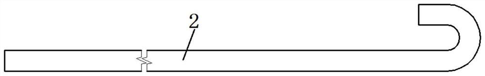
[0036] see figure 1 , 2 Or 3, one end of the reinforced rod cone 1 is conical, the other end has a smooth end surface and is welded to one end of the threaded steel bar 2, and the end of the threaded steel bar 2 away from the reinforced rod cone 1 is a hook structure , the bending angle of the hook structure on the rebar 2 is 180°.

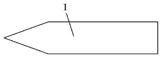
[0037] The reinforced rod cone 1 can be processed from light round steel bars. The reinforced rod cone 1 includes a connected conical section and a cylindrical section. The end face of the cylindrical section away from the conical section is connected to the threaded steel bar 2. The cylindrical section The diameter is 4mm larger than the diameter of the threaded steel bar 2.

[0038] see Figure 4 , the rubber limit fixture 3 includes a main ...

Embodiment 2

[0044] see Figure 5 , this embodiment discloses a construction method based on a grouting-free soil nailing device suitable for temporary slope support described in Embodiment 1, comprising the following steps:

[0045]1) Make several reinforced rod cones 1, several threaded steel bars 2 and some rubber limit clamps 3; wherein, the reinforced rod cones 1 are cut and polished for smooth round steel bars to form one end It is a cone head, and the other end is a rod-shaped part with a flat cross section; when making the threaded steel bar 2, according to the design requirements of the pre-reinforced slope, intercept the threaded steel bar of the corresponding length, cut one end flat, and bend the other end Make the crotch of 180 degrees; When making described rubber limit fixture 3, hard rubber tube is cut into the section length of 20cm, and one end is cut into inclined-plane along the tube length direction, is convenient when being pressed into soil body, Reduce the resistan...

Embodiment 3

[0055] This embodiment discloses a grouting-free soil nailing device suitable for temporary support of slopes, which includes a reinforced rod cone 1 , threaded steel bars 2 and rubber limit clamps 3 .

[0056] see figure 1 , 2 Or 3, one end of the reinforced rod cone 1 is conical, and the other end is connected to one end of the threaded steel bar 2, and the end of the threaded steel bar 2 away from the reinforced rod cone 1 is a hook structure.

[0057] see Figure 4 , the rubber limit clamp 3 includes a main body 301, a closing mouth 302 and a number of thorns 303 all made of rubber materials, the main body 301 is a cylindrical structure, one end of the main body 301 is connected with a conical closing mouth 302, and the other end is connected There are several spines 303 arranged at equal intervals along the circumference of the main body 301 . Figure 4 middle, Figure 4 a represents the natural state of some of the spines 303, Figure 4 b represents a state in which...


PUM

PropertyMeasurementUnit
Bending angleaaaaaaaaaa

Abstract

The invention discloses a construction method of a grouting-free soil nail device suitable for temporary support of a side slope. The construction method comprises the following steps that (1) a plurality of reinforced rod piece cones, a plurality of twisted steel bars and a plurality of rubber limiting clamps are manufactured; (2) each twisted steel bar is sleeved with a plurality of rubber limiting clamps and fixed, and then the reinforced rod piece cone and the twisted steel bars are welded to form the grouting-free soil nail device; (3) a temporary side slope or a foundation pit slope surface is excavated; (4) a plurality of grouting-free soil nail devices are pressed into the side slope, and the hook structures are exposed; 5) binding a slope surface reinforcing mesh on the surface of the slope, and fixing the slope surface reinforcing mesh with the hook structure; (6) concrete is sprayed to the side slope; (7) after the concrete strength reaches the standard, the next layer of side slope is excavated; and (8) the steps (4)-(7) are repeated, and supporting of the whole slope is completed. The anti-pulling performance of the soil nail is guaranteed, and the complex procedure of grouting type soil nails is omitted.

Description

technical field [0001] The invention relates to the field of side slope temporary support, in particular to a grouting-free soil nailing device suitable for side slope temporary support and a construction method thereof. Background technique [0002] The soil nail wall is based on the principle of the new Austrian method, and the reinforced rod cone is set close to the horizontal in the slope body of the natural slope, the artificial slope or the excavated slope of the foundation pit; a steel mesh is laid on the surface of the slope, And spray a layer of concrete surface layer; the reinforced rod cone in the slope body is firmly bonded with the surrounding soil to form a complex, relying on the soil nail group to produce a reinforcement effect, and a similar gravity retaining wall formed with the surface layer The supporting structure; the in-situ reinforcement technology that improves the mechanical properties of the overall geotechnical system and thus improves the stabili...

Claims


Application Information

Patent Timeline
IPC IPC(8): E02D5/76E02D17/20E02D17/04
Inventor 郭建军王俊杰梁柳
Owner CHONGQING JIAOTONG UNIVERSITY
Why Eureka
Try Eureka