
Motor vehicle and automatic compensation brake device thereof

A brake device and self-compensation technology, which is applied in the direction of mechanical equipment, brake types, brake components, etc., can solve the problems of inability to guarantee the brake clearance, increased brake clearance, time-consuming and labor-intensive problems, etc.

Pending Publication Date: 2017-09-22
ZHEJIANG CFMOTO POWER CO LTD
View PDF8 Cites 4 Cited by
  • Summary
  • Abstract
  • Description
  • Claims
  • Application Information

AI Technical Summary

Problems solved by technology

[0003] The current disc brake device generally includes a brake disc coaxially arranged on the wheel and a brake pad that can be pushed out by the push device. Braking, but after the above-mentioned brake device is used for a period of time, due to wear and tear, the brake clearance increases and the braking sensitivity decreases. At this time, it is often necessary to manually adjust the brake clearance, such as adding spacers on the brake disc or by adjusting The position of the moving plate, the above method is time-consuming and labor-intensive, and the second cannot be adjusted at any time with the wear of the brake pad and brake disc to ensure the brake clearance

Method used


Image

  • Motor vehicle and automatic compensation brake device thereof
  • Motor vehicle and automatic compensation brake device thereof

Examples


Embodiment Construction

[0025] The invention provides a motor vehicle and a self-compensating braking device thereof to achieve the purpose of adjusting the braking gap at any time with the wear of the brake pad and the brake disc, reducing the adjustment difficulty and saving time.

[0026] The following will clearly and completely describe the technical solutions in the embodiments of the present invention with reference to the accompanying drawings in the embodiments of the present invention. Obviously, the described embodiments are only some, not all, embodiments of the present invention. Based on the embodiments of the present invention, all other embodiments obtained by persons of ordinary skill in the art without making creative efforts belong to the protection scope of the present invention.

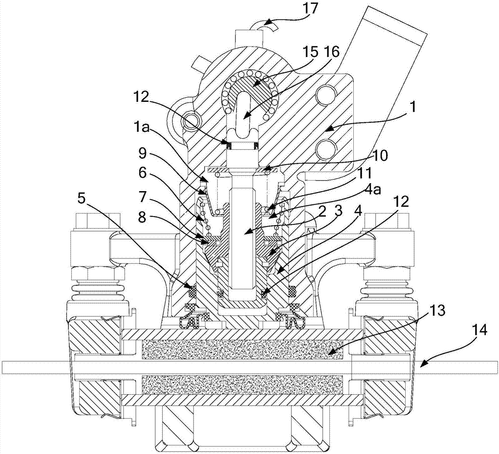
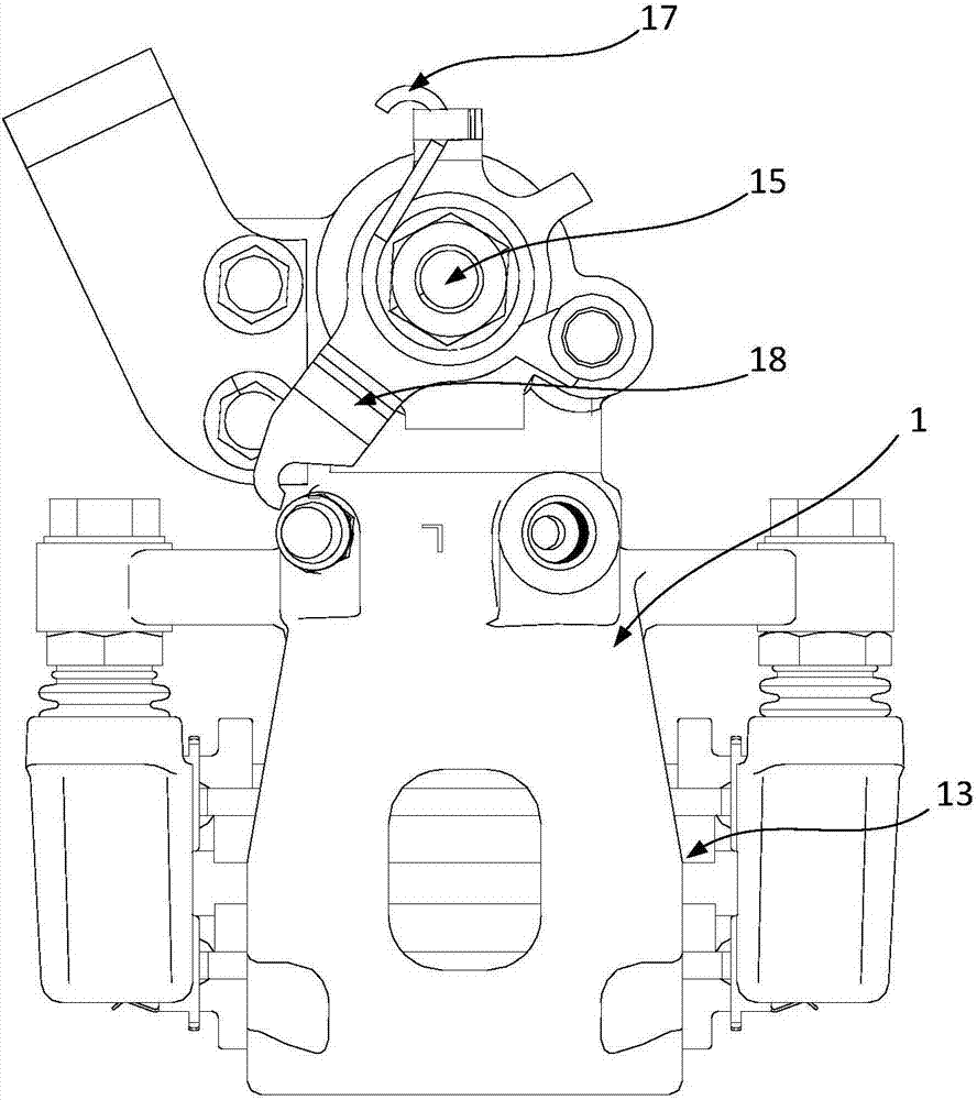
[0027] see figure 1 , figure 1 A schematic diagram of the internal structure of the self-compensating braking device provided by the embodiment of the present invention.

[0028] A self-compensating b...


PUM


Abstract

The invention discloses an automatic compensation brake device which comprises a caliper body and a pushing device. The pushing device is used for pushing a brake block for braking and comprises a pushing rod, a screw sleeve and a piston. The piston is telescopically arranged on the caliper body through an elastic fixing part. A drive cavity for containing the pushing rod and the screw sleeve is defined by the piston and the caliper body. The pushing rod is arranged in the drive cavity in a sliding manner. The screw sleeve is in screw joint to the pushing rod in the manner of rotating freely. A pre-tightening mechanism is arranged between the screw sleeve and the piston and used for pushing the screw sleeve to rotate and moving in the axial direction of the pushing rod so as to abut against the piston all the time. Through the above structure, along with wear of the brake block and a brake disc, the piston can stretch out gradually therewith, and therefore automatic compensation adjustment of a brake clearance is achieved; no manual operation is needed; time is saved; adjusting difficulty is reduced; it can be guaranteed that the brake clearance is within the preset range all the time; and brake sensitivity can be guaranteed. The invention discloses a motor vehicle.

Description

technical field [0001] The invention relates to the technical field of motor vehicles, in particular to a motor vehicle and a self-compensating brake device thereof. Background technique [0002] Disc brakes have been widely used in various vehicles due to their advantages such as sensitivity, high strength, and not easy to cause thermal attenuation. [0003] The current disc brake device generally includes a brake disc coaxially arranged on the wheel and a brake pad that can be pushed out by the push device. Braking, but after the above-mentioned brake device is used for a period of time, due to wear and tear, the brake clearance increases and the braking sensitivity decreases. For the position of the moving plate, the above-mentioned method is time-consuming and labor-intensive, and secondly, it cannot be adjusted at any time with the wear of the brake pad and the brake disc to ensure the brake clearance. [0004] Therefore, how to provide a brake device that can adjust ...

Claims


Application Information

Patent Timeline
Patent Type & Authority Applications(China)
IPC IPC(8): F16D55/226F16D65/56
CPCF16D55/226F16D65/567F16D2055/0004F16D2121/14F16D2123/00F16D2121/04F16D2125/40F16D65/18
Inventor 赖民杰陈志勇张晓雷梁海峰刘勇军
Owner ZHEJIANG CFMOTO POWER CO LTD
Learn More