Automatic reciprocating fluid valve

An automatic reciprocating and reciprocating valve technology, applied in valve details, multi-port valves, valve devices, etc., can solve the problems of high failure rate of solenoid valves and difficult to solve heat dissipation problems.

Inactive Publication Date: 2017-09-22
无锡市锡蒙机电科技有限公司
View PDF8 Cites 1 Cited by
  • Summary
  • Abstract
  • Description
  • Claims
  • Application Information

AI Technical Summary

Problems solved by technology

[0003] In the prior art, during the reciprocating motion of the fluid actuator, an electromagnetic or manual valve needs to be installed at the power end, and the failure rate of the electromagnetic valve is high; at the same time, because a large amount of fluid needs to flow back into the pump, the problem of heat dissipation is difficult to solve

Method used


Image

  • Automatic reciprocating fluid valve

Examples


Embodiment

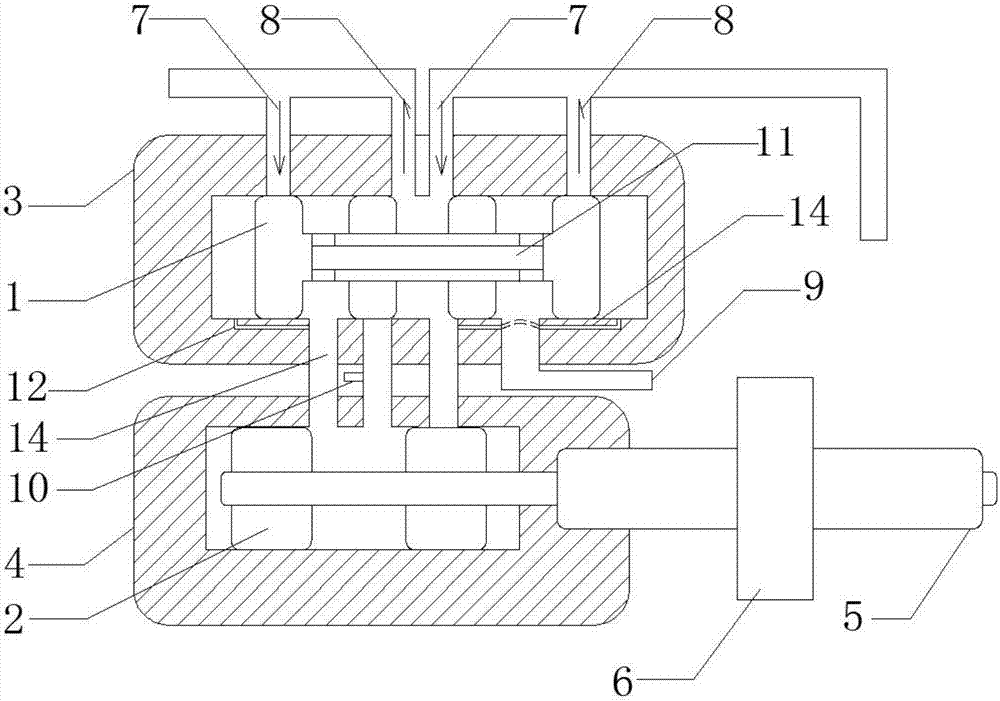
[0016] Such as figure 1 As shown, an automatic reciprocating fluid valve includes a reciprocating valve core 1, a reversing valve core 2, a reciprocating valve body 3, a reversing valve body 4, a mechanical connecting rod 5 and a piston 6, and the reciprocating valve body 3 and the reversing valve body The valve bodies 4 are all hollow cavities; the piston 6 is located outside the reversing valve body 4 and is set on one end of the mechanical connecting rod 5, and the reversing valve core 2 is located inside the cavity of the reversing valve body 4 and is set on the The other end of the mechanical linkage 5; the reciprocating valve core 1 is located inside the cavity of the reciprocating valve body 3, and the upper end of the reciprocating valve body 3 is provided with two fluid inlets 7 and two fluid outlets 8, and the reciprocating valve body The lower end of the 3 is provided with a fluid reversing port 9, and the lower end of the reciprocating valve body 3 is connected to ...


PUM


Abstract

The invention provides an automatic reciprocating fluid valve, which relates to the field of valves and includes a reciprocating valve core, a reversing valve core, a reciprocating valve body, a reversing valve body, a mechanical connecting rod and a piston, and the reciprocating valve body and the reversing valve body are both It is a hollow cavity; the piston is located outside the reversing valve body and sleeved on one end of the mechanical connecting rod, and the reversing valve core is located inside the reversing valve body cavity and is sleeved on the other end of the mechanical connecting rod; the reciprocating The valve core is located inside the cavity of the reciprocating valve body, and the upper end of the reciprocating valve body is provided with two fluid inlets and two fluid outlets; this device uses the power of the fluid itself to realize the automatic reversing of the fluid during the reciprocating movement of the fluid actuator. , there is no need to configure electromagnetic or manual valves at the power end. By installing this device on the actuator, the reciprocating speed of the actuator can be accelerated, and the work efficiency can be improved. Because the electromagnetic valve is not used, the failure rate can be reduced.

Description

technical field [0001] The invention relates to the field of valves, in particular to an automatic reciprocating fluid valve. Background technique [0002] Fluid valves are valves that control fluid flow by changing the cross section or length. A one-way throttle valve can be combined by connecting the throttle valve and the one-way valve in parallel. Throttle valve and one-way throttle valve are simple flow control valves. In the quantitative pump hydraulic system, the throttle valve and overflow valve can be combined to form three kinds of throttling speed regulation systems, that is, throttling and speed regulation of the oil inlet circuit. system, oil return throttling speed regulating system and bypass throttling speed regulating system. [0003] In the prior art, during the reciprocating motion of the fluid actuator, an electromagnetic or manual valve needs to be installed at the power end, and the failure rate of the electromagnetic valve is high. At the same time, ...

Claims


Application Information

Patent Timeline
Patent Type & Authority Applications(China)
IPC IPC(8): F16K11/07F16K31/363
CPCF16K11/07F16K31/363
Inventor 王铭明
Owner 无锡市锡蒙机电科技有限公司
Why Eureka
Try Eureka