Pneumatic oil hydraulic pump

An oil pressure and pump technology, applied in the field of hydraulic systems, can solve problems such as slow response, unstable oil supply, and low hydraulic pressure, and achieve good boosting effect, simple and reasonable structure, and good stability

Pending Publication Date: 2019-10-18
山田顺精密机械(苏州)有限公司
View PDF9 Cites 0 Cited by
  • Summary
  • Abstract
  • Description
  • Claims
  • Application Information

AI Technical Summary

Problems solved by technology

[0003] In order to solve the above-mentioned technical problems, the present invention provides a pneumatic oil pressure pump. Aiming at the deficiencies in the prior art, the air path is automatically switched by switching the shaft cylinder to realize the high-speed reciprocating motion of the actuating rod, thereby continuously and stably supplying oil , which solves the problems of slow response speed, unstable oil supply and low hydraulic pressure in the existing pneumatic hydraulic pump

Method used


Image

  • Pneumatic oil hydraulic pump
  • Pneumatic oil hydraulic pump
  • Pneumatic oil hydraulic pump

Examples


Embodiment Construction

[0028] The following will clearly and completely describe the technical solutions in the embodiments of the present invention with reference to the accompanying drawings in the embodiments of the present invention. Obviously, the described embodiments are only some, not all, embodiments of the present invention. Based on the embodiments of the present invention, all other embodiments obtained by persons of ordinary skill in the art without creative efforts fall within the protection scope of the present invention.

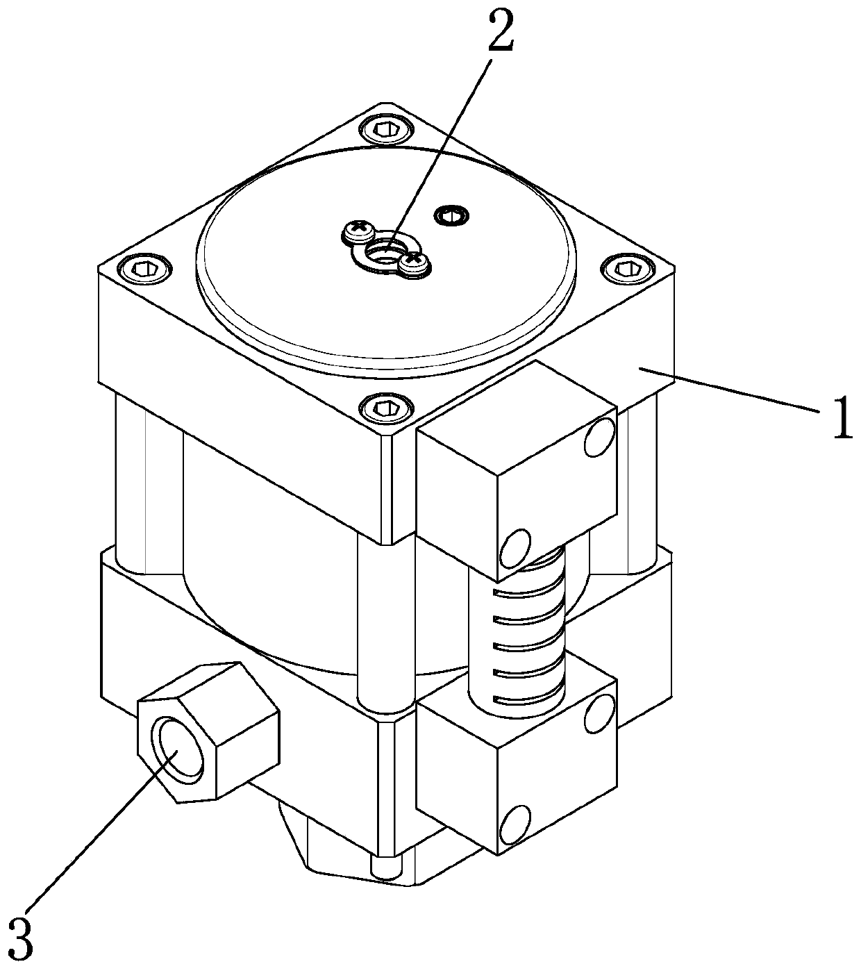
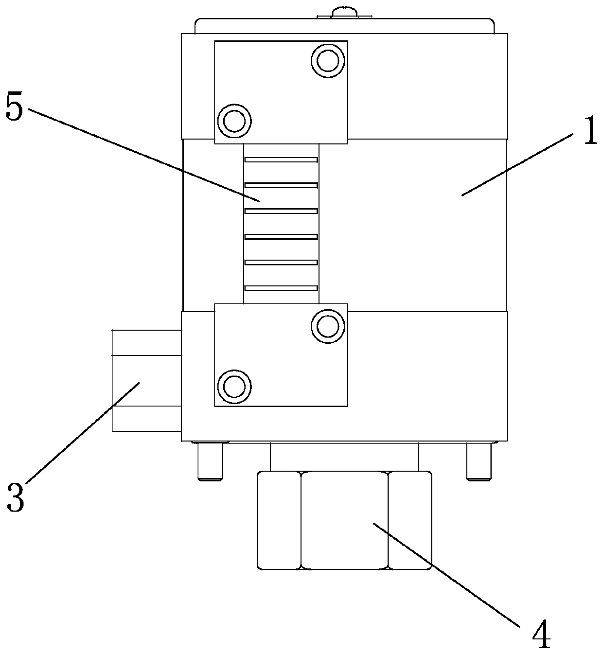
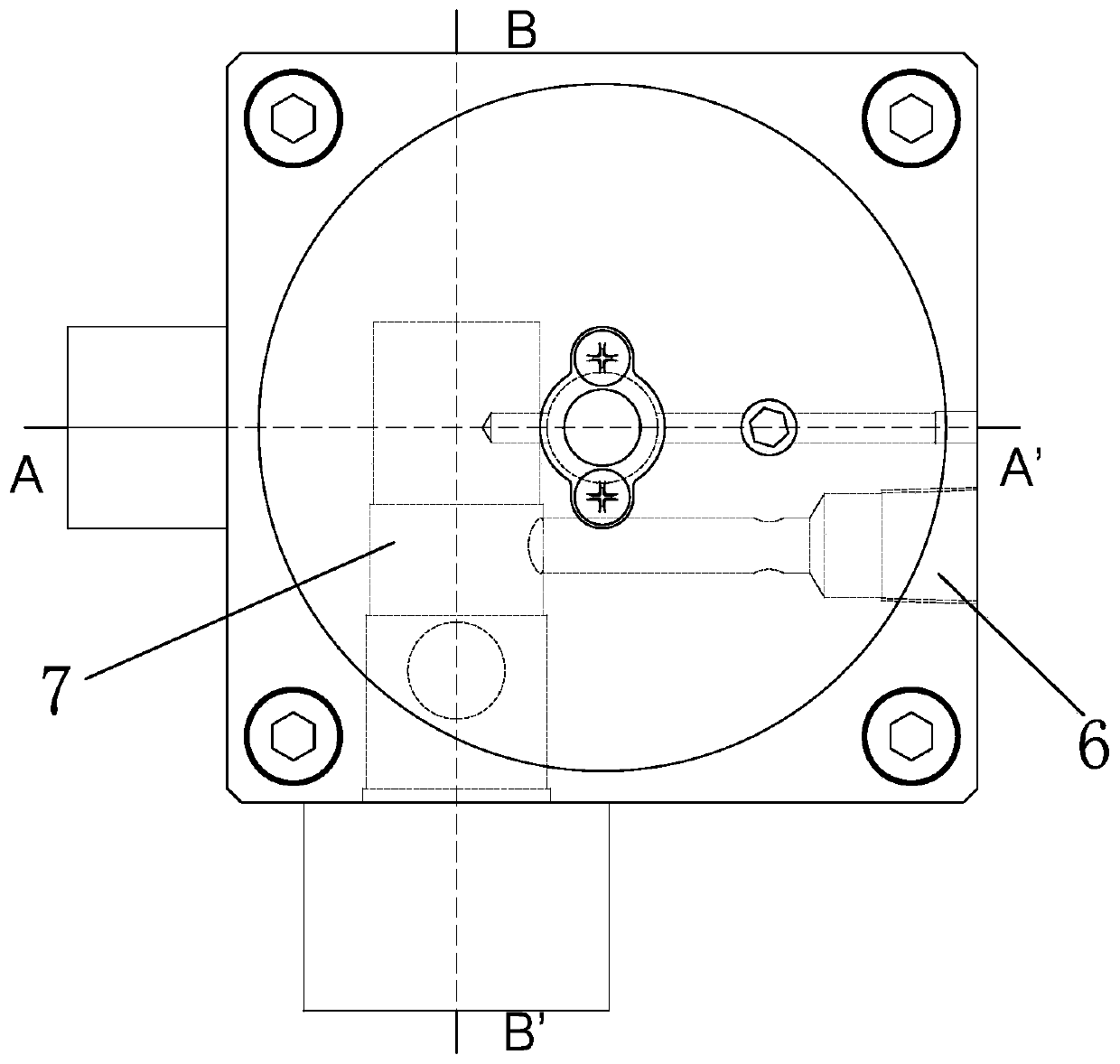
[0029] combine Figure 1 to Figure 7 , the present invention provides a pneumatic hydraulic pump, as an energy device of a hydraulic system, including a pump body 1, and an actuating component installed in the pump body 1, an oil circuit system and an air circuit system.

[0030] The actuating component performs reciprocating motion under the action of the air circuit system, and converts the mechanical energy into the pressure energy of the liquid through the oil ...


PUM


Abstract

The invention discloses a pneumatic oil hydraulic pump which comprises a pump body, an actuating assembly, an oil circuit system and a gas path system. The actuating assembly comprises an actuating rod, a main piston and a reset spring; the main piston is fixedly arranged on the actuating rod in a sleeving way; the reset spring is connected with the main piston and is arranged outside the actuating rod in a sleeving way; the oil circuit system comprises an oil chamber; an oil inlet and an oil outlet are connected onto the oil chamber; a first one-way valve is arranged on the oil inlet; a second one-way valve is arranged on the oil outlet; the lower end of the actuating rod stretches into the oil chamber; and the gas path system comprises a piston chamber, a switching shaft cylinder, a gasinlet hole, a switching gas hole and an auxiliary gas outlet hole. The pneumatic oil hydraulic pump provided by the invention is simple and reasonable in structure; and the switching shaft cylinder can smoothly switch a gas path, so that the actuating rod quickly moves in a reciprocating way, the reaction speed is fast, oil supply can be continuously and stably realized, the oil pressure is stable, meanwhile, a good pressurizing effect can be achieved, and ultrahigh hydraulic pressure is provided.

Description

technical field [0001] The invention relates to the field of hydraulic systems, in particular to a pneumatic oil pressure pump. Background technique [0002] Hydraulic transmission uses liquid as the working medium, and uses the pressure energy of the liquid to transmit power. Hydraulic pressure is widely used in industrial and civil industries due to its characteristics of large transmission power, easy transmission and configuration. The function of the actuators (hydraulic cylinder and hydraulic motor) of the hydraulic system is to convert the pressure energy of the liquid into mechanical energy, so as to obtain the required linear reciprocating motion or rotary motion. During the action of the actuators of the hydraulic system, it is necessary to supply oil (into oil) and return oil to the hydraulic actuators, and control the hydraulic actuators through oil pressure. The function of the energy device (oil pressure pump) of the hydraulic system is to convert the mechani...

Claims


Application Information

Patent Timeline
Patent Type & Authority Applications(China)
IPC IPC(8): F04B9/127F04B53/16F04B53/14F04B53/10
CPCF04B9/127F04B53/162F04B53/14F04B53/10
Inventor 谢文乔张家衡
Owner 山田顺精密机械(苏州)有限公司
Why Eureka
Try Eureka