Selfie stick
A selfie stick and clockwork technology, applied in the field of selfie sticks, can solve the problems of thick rack, increase the volume of the handle of the selfie stick, limit the minimum winding diameter of the rack, etc. Effect
- Summary
- Abstract
- Description
- Claims
- Application Information
AI Technical Summary
Problems solved by technology
Method used
Image

Examples
no. 1 approach
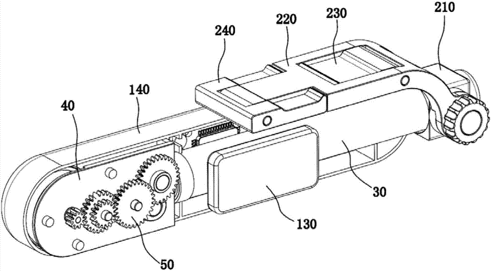
[0127] Such as Figure 3 to Figure 8 As shown, the power output part 580 is an active pressing roller in contact with the mainspring 710. The active pressing roller is a cylinder, and the power output part 580 is rotatably installed on the support frame 40. The axis of the power output part 580 (that is, The center line of rotation of the power output member 580) is parallel to the axis of the motor 510, the width direction of the spring 710 is parallel to the axis of the power output member 580, and the outer circular surface of the power output member 580 is in line with the thickness direction on the spring 710 The vertical sides are in contact with each other. In the length direction of the handle part 10 , the power output part 580 is located between the motor 510 and the telescopic assembly 30 , and the position of the motor 510 is located at the rear end of the handle body 140 (that is, the rear end of the handle part 10 ).
[0128] Preferably, the power output member ...
no. 2 approach
[0146] Such as Figure 14 to Figure 19 As shown, the difference between this embodiment and the first embodiment mainly lies in the structural form of the power output member 580 and the transmission mechanism of the telescopic control device. The telescopic control device of this embodiment does not have an elastic support mechanism and a driven pressure mechanism. Coupling rollers and other components.
[0147] Such as Figure 15 and Figure 18 As shown, in this embodiment, the power output component 580 is a first worm with a helical groove, and the clockwork 710 has a slot 730 engaged with the first worm, and the slot 730 is on the clockwork 710 along the thickness direction Through the rectangular groove provided, when the first worm rotates, it can drive the mainspring 710 to move. The first worm is a cylinder whose outer surface is provided with a spiral groove. The center line of rotation of the first worm (that is, the axis of the first worm) is parallel to the len...
no. 3 approach
[0158] The difference between this embodiment and the second embodiment mainly lies in the structural form of the power output part and the transmission mechanism of the telescopic control device, and the rest are the same. This embodiment is an improvement based on the second embodiment.
[0159] In this embodiment, the power output component is a sprocket, and the mainspring 710 has a locking groove 730 meshed with the sprocket, and the locking groove 730 is a rectangular groove provided through the mainspring 710 along the thickness direction. When the sprocket rotates, The mainspring 710 can be driven to move. The sprocket is a member with a plurality of convex teeth evenly distributed on the outer circle. The rotation centerline of the sprocket (ie, the axis of the sprocket) is parallel to the axis of the motor shaft of the motor. The convex teeth on the sprocket are embedded in the mainspring 710 The engagement with the mainspring 710 is realized in the slot 730 provide...
PUM
 Abstract
Description
Claims
Application Information
 - Generate Ideas
- Intellectual Property
- Life Sciences
- Materials
- Tech Scout
- Unparalleled Data Quality
- Higher Quality Content
- 60% Fewer Hallucinations
Browse by: Latest US Patents, China's latest patents, Technical Efficacy Thesaurus, Application Domain, Technology Topic, Popular Technical Reports.
© 2025 PatSnap. All rights reserved.Legal|Privacy policy|Modern Slavery Act Transparency Statement|Sitemap|About US| Contact US: help@patsnap.com