
Split type equal-strength beam optical fiber grating acceleration sensor

A technology of acceleration sensor and equal-strength beam, which is applied in the direction of acceleration measurement, instrument, and measuring device using inertial force, which can solve the problems of adverse effects on measurement results, poor torsion resistance, and large lateral effect, etc., and achieve improved sensitivity and increased Sensitivity, easy installation effect

Active Publication Date: 2017-09-22
OCEAN UNIV OF CHINA
View PDF13 Cites 4 Cited by
  • Summary
  • Abstract
  • Description
  • Claims
  • Application Information

AI Technical Summary

Problems solved by technology

The commonly used elastic element of the acceleration sensor is a single cantilever beam, which has poor torsion resistance in the non-measurement direction and a large lateral effect, which will adversely affect the measurement results

Method used


Image

  • Split type equal-strength beam optical fiber grating acceleration sensor
  • Split type equal-strength beam optical fiber grating acceleration sensor
  • Split type equal-strength beam optical fiber grating acceleration sensor

Examples


Embodiment 1

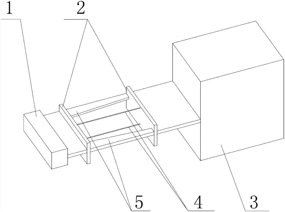
[0025] like figure 1 As shown, the split-type equal-intensity beam fiber grating acceleration sensor of the present invention includes a base 1, a sensitization part 2, a mass 3, a fiber grating 4 and a split-type equal-intensity beam 5, and the sensitization part 2 includes two Two sensitizing plates parallel in vertical direction, the two sensitizing plates include sensitizing plate I and sensitizing plate II, the sensitizing plate I is fixedly connected to the mass block 3, and the sensitizing plate II is fixedly connected to the base 1. The split equal strength beam 5 is arranged between the two sensitizing plates, one end of the split equal strength beam 5 is fixedly connected to the sensitizing plate I, and the other end of the split equal strength beam 5 is fixedly connected to the sensitizing plate II .

[0026] The equal-strength beam in the present invention divides the existing single equal-strength beam into two symmetrical beams of the same size along the center ...

Embodiment 2

[0038] The difference from Embodiment 1 is that a fiber grating is fixedly arranged between the two sensitization plates, and the fiber grating is located at the upper end or the lower end of the sensitization plate.

[0039] Others are with embodiment 1.

Embodiment 3

[0041] The difference from Example 1 is that the upper surfaces of the two sensitizing plates are located above the upper surfaces of the split equal-strength beams, and the lower surfaces of the two sensitizing plates are flush with the lower surfaces of the split equal-strength beams. A fiber grating is fixedly arranged between the two sensitization plates, and the fiber grating is located at the upper end of the sensitization plate.

[0042] Others are with embodiment 1.


PUM


Abstract

The present invention belongs to the vibration test field and relates to a split type equal-strength beam optical fiber grating acceleration sensor. The split type equal-strength beam optical fiber grating acceleration sensor comprises a base, a mass block, an optical fiber grating and a split type equal-strength beam; the split type equal-strength beam optical fiber grating acceleration sensor further comprises a sensitizing portion; the sensitizing portion comprises two parallel sensitizing plates arranged in a vertical direction; the two sensitizing plates comprise a sensitizing plate I and a sensitizing plate II; the sensitizing plate I is fixedly connected with the mass block; the sensitizing plate II is fixedly connected with the base; the split type equal-strength beam is arranged between the two sensitizing plates; one end of the split type equal-strength beam is fixedly connected with the sensitizing plate I, and the other end of the split type equal-strength beam is fixedly connected with the sensitizing plate II; the thickness of the sensitizing plates in the vertical direction is greater than the thickness of the equal-strength beam; the split type equal-strength beam includes two symmetrical beams; the two beams are arranged symmetrically with a gap left therebetween; the optical fiber grating is arranged between the sensitizing plate I and the sensitizing plate II; and two ends of the optical fiber grating are fixedly connected with the sensitizing plate I and the sensitizing plate II respectively. The sensor has the advantages of high sensitivity, high torsional rigidity and small lateral effect.

Description

technical field [0001] The invention relates to the field of vibration testing, in particular to a split-type equal-intensity beam fiber grating acceleration sensor. Background technique [0002] Vibration problems widely exist in life and production. Buildings, machines, etc. will vibrate under internal or external excitation. However, mechanical vibration often destroys the normal operation of the machine, and even reduces the service life of the machine and causes irreversible damage to the machine. Most mechanical vibrations are harmful. With the development of modern industry and modern science and technology, low-vibration and low-noise requirements are put forward for various instruments and equipment, as well as monitoring and diagnosis of main production processes or important equipment, and control of the working environment. Therefore, the research on vibration is not only conducive to improving the living environment and living standards, but also helps to impr...

Claims


Application Information

Patent Timeline
IPC IPC(8): G01H9/00G01P15/03
CPCG01H9/004G01P15/03Y02T90/00
Inventor 杨永春聂修逸陈常龙崔银峰
Owner OCEAN UNIV OF CHINA
Learn More