Wall-through or pipe-through variable-diameter sealing structure of cable and sealing method of variable-diameter sealing structure

A sealing structure and cable technology, applied in electrical components and other directions, can solve personal safety accidents, affect the safety and use of power grids, accelerate insulation aging, etc., and achieve the effect of simple and convenient sealing methods, breaking through technical bottlenecks, and reducing construction problems.

Inactive Publication Date: 2017-09-22
CHANGYUAN ELECTRIC TECH
View PDF5 Cites 1 Cited by
  • Summary
  • Abstract
  • Description
  • Claims
  • Application Information

AI Technical Summary

Problems solved by technology

[0003] This sealing method of mud plugging has the problems of corroding cables, not suitable for outdoor humid, extremely cold and extremely hot working environments, and is prone to paint peeling, moisture failure, and oil seepage when the temperature is high; this leads to long-term immersion of cables in water. In this case, the insulation layer of the outer sheath of the cable is corroded, and the insulation performance fails. Under the action of alternating current, the metal shield of the cable forms a circulating current, which causes the cable to heat up and accelerate the aging of the insulation, and finally leads to a cable breakdown accident, which affects the stability of the power supply of the entire power grid. What's more Otherwise, it may cause personal safety accidents; if the sealing does not work, small animals may even climb into the cable and switch connection compartment, which will easily cause power failure accidents such as short circuit or tripping, and poor sealing will lead to various safety accidents. generated, seriously affecting the safety and use of the power grid

Method used


Image

  • Wall-through or pipe-through variable-diameter sealing structure of cable and sealing method of variable-diameter sealing structure
  • Wall-through or pipe-through variable-diameter sealing structure of cable and sealing method of variable-diameter sealing structure
  • Wall-through or pipe-through variable-diameter sealing structure of cable and sealing method of variable-diameter sealing structure

Examples


Embodiment Construction

[0024] The idea, specific structure and technical effects of the present invention will be clearly and completely described below in conjunction with the embodiments and accompanying drawings, so as to fully understand the purpose, features and effects of the present invention. Apparently, the described embodiments are only some of the embodiments of the present invention, rather than all of them. Based on the embodiments of the present invention, other embodiments obtained by those skilled in the art without creative efforts belong to The protection scope of the present invention.

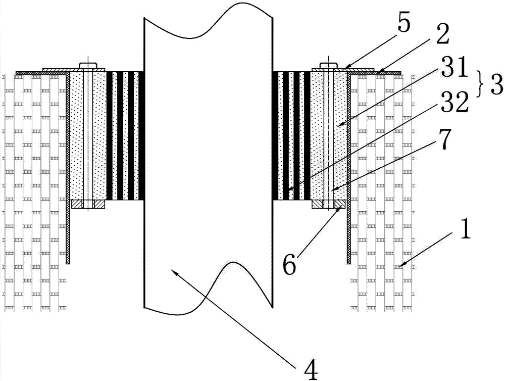
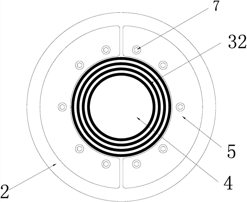
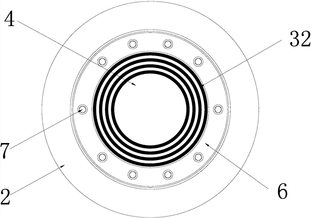
[0025] refer to Figure 1 to Figure 3 , a variable-diameter sealing structure for cables passing through walls or pipes, including an installation body 1, and an installation hole is opened on the installation body 1, and a base sleeve 2 is fixed in the installation hole, and the base There is a flexible sealing layer 3 fixed inside the sleeve 2, and the base sleeve 2 is used to isolate the flexi...


PUM


Abstract

The invention discloses a variable-diameter sealing structure and a sealing method for cables passing through walls or pipes. The installation body is provided with an installation hole, and a base sleeve is fixed in the installation hole. The base A flexible sealing layer is fixed inside the sleeve, and the cable is passed through the central through hole of the flexible sealing layer. The inner and outer end faces of the flexible sealing layer are respectively fixed with an upper gland flange and a lower gland flange. The flange is pressed against the outer end surface of the base sleeve, and the upper gland flange, flexible sealing layer and lower gland flange are fixed together by a connecting rod; the flexible sealing layer is made of flexible material, which solves the problem of Cable breakdown accidents caused by long-term immersion of cables due to the inability of the existing sealing materials to be tightly sealed with cables and wall pipes; it is also reserved for future expansion, reducing upgrade maintenance and unintentional construction problems, and bringing new benefits to installation, commissioning and maintenance. For great convenience.

Description

technical field [0001] The invention relates to the field of electric equipment, and relates to laying cables through walls or pipes, in particular to a variable-diameter sealing structure and a sealing method for cables passing through walls or pipes. Background technique [0002] With the development of the economy and the advancement of technology, as well as the progress of urban power grid reconstruction projects, it has become a trend for power cables to replace overhead lines, especially polymer insulated power cables represented by cross-linked polyethylene (XLPE) insulation, which have The advantages of good insulation performance, large transmission capacity, simple accessories, light structure, and not limited by height drop occupy an absolute dominant position in the field of cable applications. Most XLPE cables are laid by direct burial, through pipes, through walls or tunnels, etc., and cable seals are required at the places where cables pass through walls and ...

Claims


Application Information

Patent Timeline
Patent Type & Authority Applications(China)
IPC IPC(8): H02G3/22
CPCH02G3/22
Inventor 胡飞强卫刘夏张俊杰黄成龙夏云杰梁振杰
Owner CHANGYUAN ELECTRIC TECH
Why Eureka
Try Eureka