
Front roller bearing for drawing frame

A technology for drawing frames and bearings, which is applied to spinning machines, continuous winding spinning machines, textiles and papermaking, etc. It can solve problems affecting sliver, increased bearing resistance, lack of oil in bearings, etc., and achieves extension Refueling cycle, avoid heat damage, ensure the effect of lubrication effect

Inactive Publication Date: 2017-09-26
合肥宝创电子科技有限公司
View PDF2 Cites 0 Cited by
  • Summary
  • Abstract
  • Description
  • Claims
  • Application Information

AI Technical Summary

Problems solved by technology

[0002] The speed of the front roller of the draw frame is very fast during production, and the four needle roller bearings used in conjunction with it tend to heat up after a period of operation, resulting in increased or damaged bearing resistance, causing the front roller to bend and deform, and affecting the sliver.
After analysis, the reasons for the bearing heating are: (1) When the needle roller bearing is running at high speed, because there is no sealing ring, the grease overflows from the side, resulting in the lack of oil in the bearing; It overflows unobstructed, and the bearing oil gap is not filled enough, which cannot meet the lubrication requirements; (2) Because there is no sealing ring, flying flowers and dust are easily involved in the bearing
These two factors cause the bearing to heat up until it is damaged
In addition, there are five sealing rings on the side of the bearing, and there is a lot of oil on the bearing side, which also increases the difficulty of cleaning by the lathe

Method used

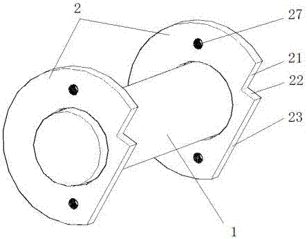
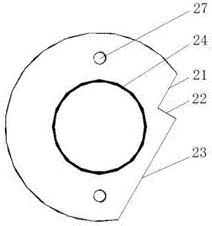
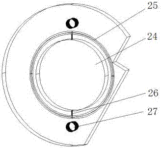

Image

  • Front roller bearing for drawing frame
  • Front roller bearing for drawing frame
  • Front roller bearing for drawing frame

Examples


Embodiment Construction

[0015] The present invention will be described in detail below with reference to the accompanying drawings and in combination with embodiments.

[0016] Such as Figure 1 to Figure 3 As shown, a front roller bearing of a draw frame includes a bearing 1 and retaining rings 2 symmetrically arranged on both sides of the bearing. The retaining ring 2 is made of gray cast iron. At least one fixed The screw hole 27 used, its outer ring is recessed inwardly to form the first folded edge 21 connected, the second folded edge 22 and the third folded edge 23, the first folded edge 21 and the third folded edge 23 are arranged in parallel, and the second folded edge 21 is arranged in parallel. The folded edge 22 is perpendicular to the first folded edge 21 and the third folded edge 23, and the distances from the first folded edge 21 and the third folded edge 23 to the center of the retaining ring 2 are respectively 3 / 5 of the outer diameter of the retaining ring 2 and 4 / 5 The outer diamet...


PUM


Abstract

The invention discloses a front roller bearing for a drawing frame. The front roller bearing comprises a bearing and check rings symmetrically arranged on the two sides of the bearing. The check rings are made of a grey cast iron material. Outer rings of the check rings are recessed inwards to form a first folded edge, a second folded edge and a third folded edge which are connected with each other, the first folded edge and the third folded edge are arranged in parallel. The second folded edge is perpendicular to the first folded edge and the third folded edge. The second folded edge is internally provided with an inner hole in close fit with the bearing, the periphery of the inner hole is further provided with an annular hole for storing grease, at least one oil duct is arranged between the annular hole and the inner hole, and through the oil duct, oil can be added from the inner hole to the annular hole or discharged from the annular hole to the inner hole. Grease of the front roller bearing does not overflow easily, a bearing lubrication effect is ensured, and an oil adding period is prolonged; flyings are not involved in the bearing easily, and influences on sliver evenness conditions caused by roller deformation and bending and bearing heating and damage are avoided.

Description

technical field [0001] The invention belongs to the technical field of spinning equipment, in particular to a front roller bearing of a draw frame. Background technique [0002] The speed of the front roller of the draw frame is very fast during production, and the four needle roller bearings used in conjunction with it tend to heat up after a period of operation, resulting in increased or damaged bearing resistance, causing the front roller to bend and deform, and affecting the sliver. . After analysis, the reasons for the bearing heating are: (1) When the needle roller bearing is running at high speed, because there is no sealing ring, the grease overflows from the side, resulting in the lack of oil in the bearing; It overflows without obstruction, and the bearing oil gap is not filled enough, which cannot meet the lubrication requirements; (2) Because there is no sealing ring, flying flowers and dust are easily drawn into the bearing. These two factors cause the bearing...

Claims


Application Information

Patent Timeline
IPC IPC(8): D01H1/14
CPCD01H1/14
Inventor 杜玮
Owner 合肥宝创电子科技有限公司
Learn More