Light emitting diode circuit

A light-emitting diode and circuit technology, which is applied in the field of circuit original devices, can solve the problems of heavy weight, high cost, heat dissipation, etc., and achieve the effect of saving the transformer

Inactive Publication Date: 2017-09-26
CHIA HSING ELECTRICAL
View PDF4 Cites 0 Cited by
  • Summary
  • Abstract
  • Description
  • Claims
  • Application Information

AI Technical Summary

Problems solved by technology

[0004] However, when a lamp needs to be equipped with a transformer, its overall volume is relatively large and heavy, and there are also problems of high cost and heat dissipation. Therefore, a new technical solution is urgently needed in the prior art to solve this problem. question

Method used


Image

  • Light emitting diode circuit

Examples


Embodiment Construction

[0025] In the following embodiments, the same or similar reference numerals represent the same or similar components. In addition, the directional terms mentioned in the following embodiments, such as: up, down, left, right, front or rear, etc., are only referring to the directions of the attached drawings, therefore, the directional terms used are for illustration, and It is not intended to limit the invention.

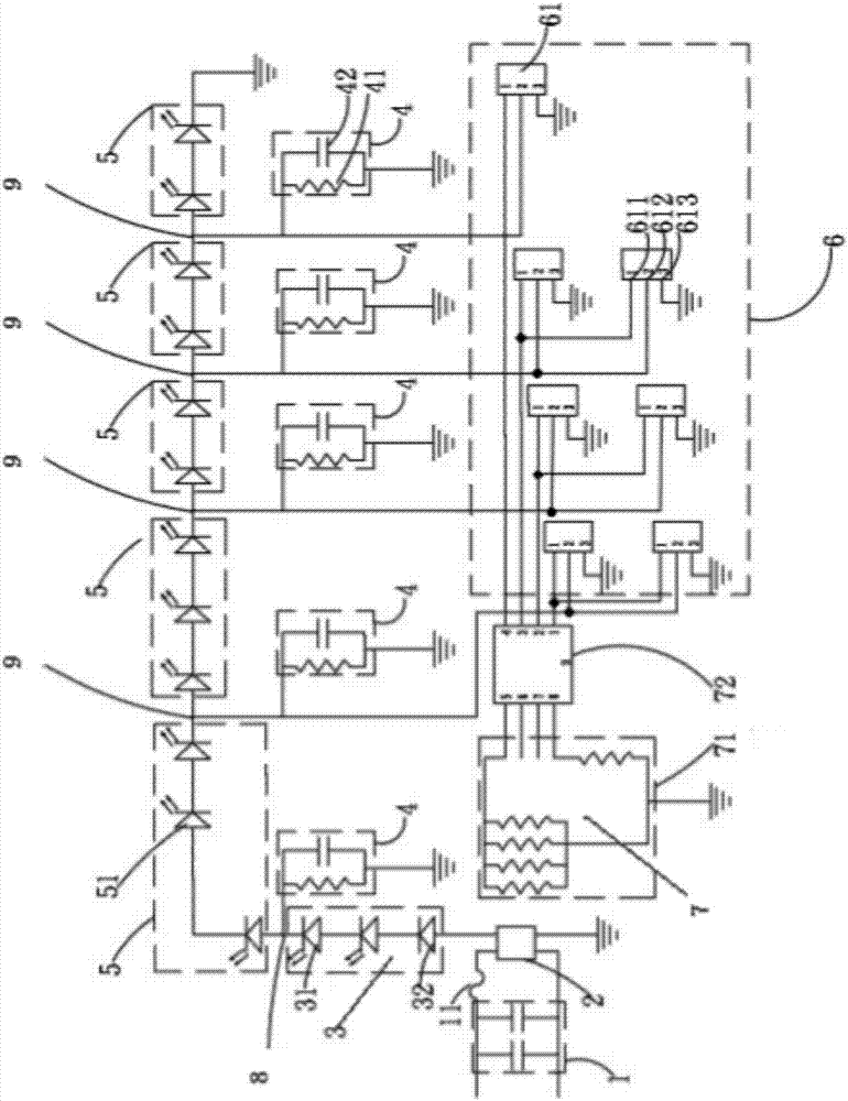
[0026] Such as figure 1 As shown, the light-emitting diode circuit includes a convex wave absorption module 1, a rectifier module 2, a first light-emitting module 3, a filter module 4, a second light-emitting module 5, a power crystal module 6, and a current regulation module 7. The convex wave The absorbing module 1 is connected to an AC power source, the source of the AC power source can be a commercial socket but not limited thereto, the convex wave absorbing module 1 is connected to the rectifying module 2, and the convex wave absorbing module 1 and A fuse 11 i...


PUM


Abstract

A light emitting diode circuit belongs to the technical field of circuit elements. The working voltage of a traditional light emitting diode is far lower than the working voltage required in traditional light emitting technology. Therefore for normal operation, connection with a transformer is required for changing the working voltage, so that normal operation of the light emitting diode can be realized. According to the light emitting diode circuit, through circuit improvement, a light emitting module can perform normal light emitting operation without the transformer, and furthermore the light emitting diode circuit with advantages of small size, small weight, low cost and high heat radiation performance is realized.

Description

technical field [0001] The invention belongs to the technical field of original circuit devices, and in particular relates to a light emitting diode. Background technique [0002] At present, with the widespread use of light-emitting diodes, the light source in many occasions has been replaced by light-emitting diodes from traditional light-emitting technologies. [0003] There are also many lamps or lighting products that are combined with light-emitting diodes. The working voltage of light-emitting diodes is much lower than that required by traditional light-emitting technologies, so in order to work normally, a transformer needs to be connected to change the working voltage so that light-emitting diodes can operate normally. [0004] However, when a lamp needs to be equipped with a transformer, its overall volume is relatively large and heavy, and there are also problems of high cost and heat dissipation. Therefore, a new technical solution is urgently needed in the prio...

Claims


Application Information

Patent Timeline
IPC IPC(8): H05B33/08H05B44/00
CPCH05B45/37
Inventor 蓝仁宏
Owner CHIA HSING ELECTRICAL
Why Eureka
Try Eureka