Cleaning device for mechanically cleaning gas nozzle of gas-shielded welding torch

A technology for gas nozzles and cleaning equipment, which is applied in the directions of cleaning welding torches, cleaning methods using tools, cleaning hollow objects, etc., can solve the problems of difficult mechanical cleaning, difficult access, high cost, and achieves simple construction and operation, and the cost is favorable , the effect of functional safety

Active Publication Date: 2017-09-26
AUDI AG
View PDF5 Cites 8 Cited by
  • Summary
  • Abstract
  • Description
  • Claims
  • Application Information

AI Technical Summary

Problems solved by technology

[0006] Due to the extremely conical design of the gas nozzle, the inner surface of the gas nozzle forming the undercut can only be touched with difficulty and therefore can only be cleaned mechanically with difficulty.
Therefore costly ultrasonic cleaning is now used
Ultrasonic cleaning is particularly complex and cost-intensive at high investment costs in robot-assisted welding / soldering methods and method-integrated automatic cleaning

Method used


Image

  • Cleaning device for mechanically cleaning gas nozzle of gas-shielded welding torch
  • Cleaning device for mechanically cleaning gas nozzle of gas-shielded welding torch
  • Cleaning device for mechanically cleaning gas nozzle of gas-shielded welding torch

Examples


Embodiment Construction

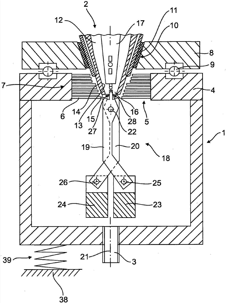
[0036] exist figure 1 shows a cross-sectional view of a cleaning head 1 of a cleaning device (not shown in further detail) for mechanically cleaning the gas nozzles 2 of a shielding gas welding torch, in particular a CMT+ welding torch. The cleaning head 1 is designed as a cylindrical hollow body in the shape of a pot or cage and can be rotated by means of a controllable rotary drive (not shown) via a central drive shaft 3 on the bottom side. The upper wall 4 of the cleaning head 1 has a central insertion opening 5 , wherein a conically shaped brush ring 7 is formed with radially inwardly facing plastic bristles 6 .

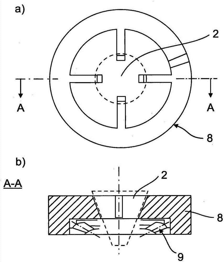
[0037] On the upper wall 4, the centering aid 8 is mounted by means of a spherical or conical bearing ring 9 in such a way that when the hollow body of the cleaning head rotates, the centering aid 8 passes through a not shown support or housing fixed in place. The connection is held in a non-rotatable manner.

[0038] The centering aid member 8 has a centering ...


PUM


Abstract

The invention relates to a cleaning device for mechanically cleaning a gas nozzle of a gas-shielded welding torch, comprising a cleaning head (1), which is rotationally driven in a controlled manner and has at least one cleaning element that rotates therewith, and comprising a feeding and centering apparatus for positioning the gas nozzle (2) coaxially with respect to the axis of rotation (21) of the cleaning head (1) in the region of the at least one cleaning element. According to the invention, the cleaning element consists of a pair of cleaning scissors (18) having two cleaning arms (19, 20), which are suspended in the cleaning head (1) on a pivot bearing (22) arranged transversely to the axis of rotation (21) in the form of a pair of scissors, in such a way that the cleaning arms can swing freely. A centrifugal-force weight (23, 24) is arranged on each of the cleaning arms (19, 20) at the lower end region facing away from the gas nozzle such that the pair of cleaning scissors (18) is spread open when the cleaning head rotates. Each of the cleaning arms (19, 20) has a scraper structure (27, 28) at the upper end region facing the gas nozzle, which scraper structures are inserted into the gas nozzle (2) in the folded-together state of the pair of cleaning scissors without rotation of the cleaning head and are pressed against the gas-nozzle inner surface (13) of the gas nozzle (2) in a sliding and scraping manner when the pair of cleaning scissors (18) is spread open by a subsequent rotation of the cleaning head, the gas nozzle being held non-rotatably.

Description

technical field [0001] The invention relates to a cleaning device for mechanically cleaning the gas nozzles of a shielding gas welding torch, in particular a CMT+ welding torch, according to the preamble of claim 1 . Background technique [0002] A shielding gas-welding torch (EP 0090233B1) for known devices for cleaning welding torches comprises a contact tube which guides the welding wire during welding and a tubular, which guides an inert shielding gas which surrounds the contact tube at a distance from it. Gas nozzle. The gas nozzle has a conically tapering gas nozzle tip. Furthermore, the contact tube is also conically tapered at the end as a truncated cone. [0003] The known cleaning device has a controlled rotationally driven cleaning head with at least one co-rotating cleaning element, and a transport and centering device for relative The axis of rotation of the cleaning head positions the gas nozzle coaxially. [0004] In particular, the gas nozzle to be cleane...

Claims


Application Information

Patent Timeline
Patent Type & Authority Applications(China)
IPC IPC(8): B08B1/04F23D14/50B08B9/02
CPCB08B1/04B08B9/021F23D14/50B05B15/52B05B15/522B23K9/328A46B9/005A46B13/001A46B2200/3013B08B1/002B08B1/005B08B9/027
Inventor K·丹泽尔
Owner AUDI AG
Why Eureka
Try Eureka