Fuel injector for operation with combustible gas

A fuel injector and gas nozzle technology, which is applied to fuel injection devices, special fuel injection devices, charging systems, etc., can solve problems such as flow loss of combustible gas, and achieve the effect of high engine power and reduced flow loss.

Active Publication Date: 2017-09-26
L'ORANGE GMBH
View PDF5 Cites 3 Cited by
  • Summary
  • Abstract
  • Description
  • Claims
  • Application Information

AI Technical Summary

Problems solved by technology

[0004] However, the disadvantage associated with the use of such fuel injectors, whose nozzle needles are each accommodated as standard in rotationally symmetrical bores, is that combustible gas flow losses occur due to the asymmetrical flow around the needle seats.

Method used


Image

  • Fuel injector for operation with combustible gas
  • Fuel injector for operation with combustible gas
  • Fuel injector for operation with combustible gas

Examples


Embodiment Construction

[0029] In the following description and drawings, the same reference numerals correspond to functionally identical or similar elements.

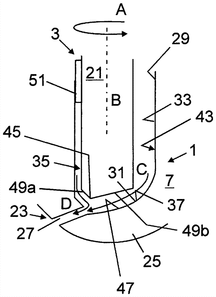
[0030] figure 1 The nozzle-side end section 1 of a fuel injector 3 according to the invention for operation with a combustible gas is shown in an exemplary and schematic manner, the fuel injector 3 shown as dual fuel-fuel injection The device is provided, that is to say not only for operation with liquid fuels but also for operation with combustible gases. As a liquid fuel for use with the fuel injector 3, diesel fuel, bio-oil, heavy oil or a liquid fuel different from these can be provided, as a combustible gas for use with the fuel injector 3, in particular natural gas can be provided , Also such as biogas, soil waste gas, etc. In addition to, for example, pure liquid fuel operation, the fuel injector 3 provided in this way is especially designed for combustion jet operation.

[0031] The fuel injector 3 has an injector housing 5 which ...


PUM


Abstract

The invention relates to a fuel injector (3) for operation with combustible gas, wherein the fuel injector (3) has, at a nozzle end (25), a gas nozzle assembly (23) having at least one gas nozzle opening (27); wherein the fuel injector (3) has at least one gas nozzle needle (21), which is associated with the gas nozzle assembly (23) and is accommodated in an axial holder (29) in such a way that the stroke of the at least one gas nozzle needle can be controlled, wherein each gas nozzle opening (27) leads out of the holder (29) having a radial direction component at the nozzle end (25); wherein the fuel injector (3) has, in the holder (29), a needle seat (31) upstream of the particular nozzle opening (27), which needle seat is provided for selectively blocking a combustible-gas flow path to the associated gas nozzle opening (27) in interaction with the gas nozzle needle (21); wherein the one or more gas nozzle openings (27) are distributed merely over part of the circumference in the circumferential direction (A) of the gas nozzle needle (21), wherein the holder (29), adjoining the needle seat (31) and extending away therefrom axially in the upstream direction, is asymmetric with respect to an axial center axis (B) through the gas nozzle needle (21), wherein the asymmetry results from a cross-section expansion (33) of the holder (29) on a side of the holder (29) that lies radially opposite the at least one gas nozzle opening (27), such that a greater mass flow rate of combustible gas can be conducted in the holder (29) by means of the cross-section expansion (33) than on the gas nozzle opening side (35) opposite thereto; wherein the holder (29) is also shaped to apply a flow direction oriented toward the radially opposite at least one gas nozzle opening (27), already upstream of the needle seat (31) and by means of the cross-section expansion (33), to a combustible-gas flow (C) guided to the needle seat (31) by the cross-section expansion (33).

Description

technical field [0001] The invention relates to a fuel injector for operation with a combustible gas according to the preamble of claim 1 . The fuel injector can especially be provided as a dual fuel-fuel injector. Background technique [0002] In the field of (large) engines, especially in stationary engines for generating electric current, gaseous fuels are becoming more and more important. Natural gas is, for example, excellently suited for economical and environmentally friendly engine operation due to its very good availability and its more favorable emission potential compared to diesel fuel. [0003] In the case of fuel injectors which are designed as multi-substance injectors or dual-fuel injectors and which, in addition to gaseous injector parts, also have liquid fuel injector parts, in particular for combustion jet operation, the fuel injector The gas nozzle holes of the fuel injector are often not distributed over the entire circumference of the fuel injector, s...

Claims


Application Information

Patent Timeline
Patent Type & Authority Applications(China)
IPC IPC(8): F02M43/04F02M21/02
CPCF02M21/0263F02M21/0275F02M21/0284F02M43/04F02M2200/44Y02T10/30
Inventor I.J.贝格尔M.卡伦博恩
Owner L'ORANGE GMBH
Why Eureka
Try Eureka