Lightguide with means to compensate for gradual losses of light along the guide

A technology of light guide and light, which is applied in the direction of light guide, light guide, optical fiber light guide, etc. of the lighting system, and can solve problems such as narrow beams

Active Publication Date: 2017-09-26
VALEO VISION SA
View PDF9 Cites 1 Cited by
  • Summary
  • Abstract
  • Description
  • Claims
  • Application Information

AI Technical Summary

Problems solved by technology

However, these measures have the disadvantage that parts of

Method used


Image

  • Lightguide with means to compensate for gradual losses of light along the guide
  • Lightguide with means to compensate for gradual losses of light along the guide
  • Lightguide with means to compensate for gradual losses of light along the guide

Examples


Embodiment Construction

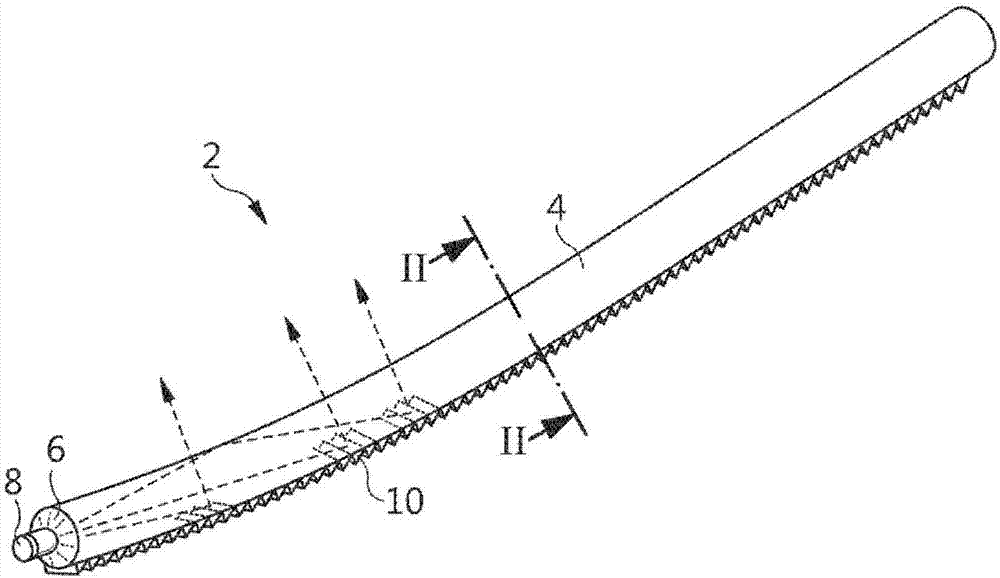
[0043] figure 1 A guiding light according to the invention is shown.

[0044] The light guide 2 comprises a transparent body 4 extending in a main direction. It can extend in straight lines, curves, or a combination of both. Its section can take various shapes, such as circular, oval or polygonal. The transparent body 4 may be made of glass or plastic material, such as in particular polycarbonate or PMMA. It has an entrance face 6 at one of its two ends, facing the entrance face 6 one or more light sources 8 are arranged. The light rays emitted by the light source 8 enter the transparent material 4 of the light guide to propagate therein by transmission and continuous reflection at the diopter formed by the outer surface of the body and the surrounding air. In fact, the body of transparent material has a higher refractive index than the surrounding air, typically around 1.5, compared to 1 for air. such as by figure 1 Rays of those rays indicated by the dashed lines in , ...


PUM


Abstract

The invention relates to a lightguide (2) including a transparent body (4) which is generally elongate in a main direction, an outer facet (12) forming a dioptre with the environment of said body, a first row (16) of angled facets (20) capable of reflecting the rays in order to output same, and at least one second row (14, 18) of reflecting facets (24) which are smaller than the corresponding reflecting facets (20) of the first row (16). The light reflected by the one or more second rows complements the light beam from the first row. The widths of the first row and the second rows can gradually increase or decrease, respectively, as the distance from the light source increases so as to compensate for the gradual losses of light passing through the lightguide.

Description

technical field [0001] The invention relates to the field of light guides, in particular light guides for motor vehicle lighting and / or signaling modules and devices. Background technique [0002] Patent document FR2871550A1 discloses a light guide for motor vehicle lighting or signaling, comprising a transparent body, generally elongated in the main direction, with diopters forming diopters with the environment of said body The outer surface, and reflective surfaces distributed along the outer surface. The reflective surface has a prismatic profile in order to deflect light rays passing through the light guide by continuous reflection at the diopter. This deflection enables the light rays under consideration to come into contact with the diopter at angles of incidence smaller than the limit angle of total reflection and thus leave the body of the light guide. The prismatic reflective surface has a profile that varies along the light guide so as to at least partially compe...

Claims


Application Information

Patent Timeline
IPC IPC(8): F21S8/10F21V8/00G02B6/00
CPCG02B6/001F21S43/237F21S43/245F21S43/247F21S43/249F21S41/24F21S41/28F21S41/322F21S43/241F21S43/26B60Q1/0011G02B6/0036
Inventor 安东尼·德朗贝特里克里斯托弗·沃勒斯
Owner VALEO VISION SA
Why Eureka
Try Eureka