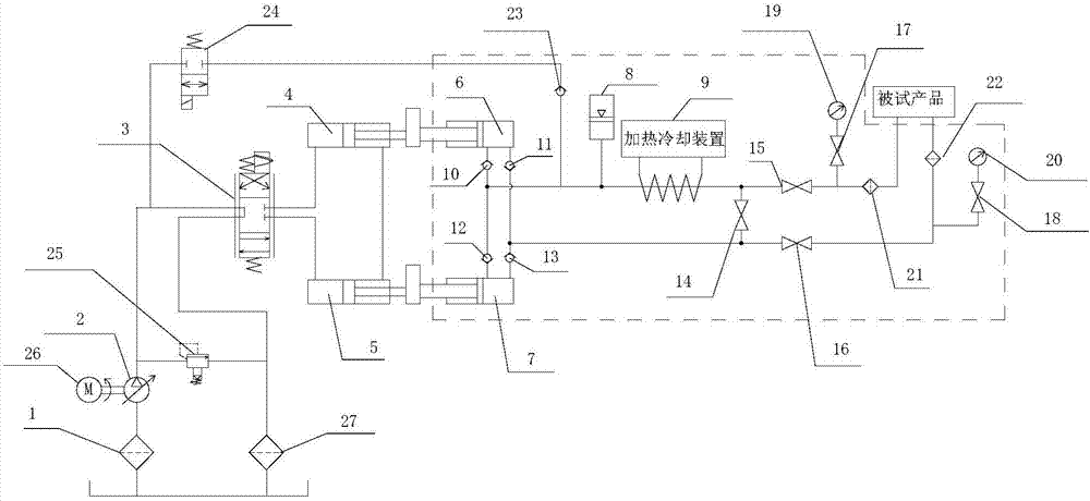
Hydraulic system for heating and cooling high-pressure oil liquid

A hydraulic system, high-pressure oil technology, applied in the direction of fluid pressure actuation system components, accumulator devices, fluid pressure actuation devices, etc., can solve problems such as unfavorable product testing, failure to work normally, and expensive hydraulic components, etc. Achieve the effect of being suitable for popularization and popularization, avoiding pressure fluctuations and reducing system fluctuations

Active Publication Date: 2017-09-29
LANDING GEAR ADVANCED MFG
View PDF8 Cites 7 Cited by
  • Summary
  • Abstract
  • Description
  • Claims
  • Application Information

AI Technical Summary

Problems solved by technology

[0002] In aerospace equipment, the minimum temperature of the oil in the hydraulic system will reach -45°C, and the maximum temperature will reach 80°C. Such a large temperature change brings difficulties to the selection of hydraulic components. Manufacturers are in the hands of a few developed countries, and some hydraulic parts are difficult to find in such a large temperature range.
On the test bench for aerospace equipment parts, it is necessary to heat or cool the hydraulic fluid entering the product to simulate the real temperature of the product, and to assess the reliability and sealing of the product. If high and low temperature hydraulic parts are used entirely, the cost will be huge rise, the service life is shortened, which is not conducive to the maintenance of the test bench, nor to the test of the product, and the reliability is greatly reduced. When the hydraulic oil is at a low temperature, the viscosity becomes larger, which will make the hydraulic pump insufficient in self-priming (the plunger pump is especially even), produce loud noise and vibration, and cannot work normally

Method used


Image

  • Hydraulic system for heating and cooling high-pressure oil liquid

Examples


Embodiment Construction

[0024] It should be noted that, in the case of no conflict, the embodiments of the present invention and the features in the embodiments can be combined with each other.

[0025] In describing the present invention, it should be understood that the terms "center", "longitudinal", "transverse", "upper", "lower", "front", "rear", "left", "right", " The orientations or positional relationships indicated by "vertical", "horizontal", "top", "bottom", "inner" and "outer" are based on the orientations or positional relationships shown in the drawings, and are only for the convenience of describing the present invention and Simplified descriptions, rather than indicating or implying that the device or element referred to must have a particular orientation, be constructed and operate in a particular orientation, and thus should not be construed as limiting the invention. In addition, the terms "first", "second", etc. are used for descriptive purposes only, and should not be understood ...


PUM


Abstract

The invention provides a hydraulic system for heating and cooling high-pressure oil liquid. The hydraulic system comprises a first hydraulic cylinder and a second hydraulic cylinder, and the first hydraulic cylinder and the second hydraulic cylinder are connected to a three-position four-way servo valve; the three-position four-way servo valve is connected to an oil tank through a hydraulic pump and an oil suction filter; the first hydraulic cylinder and the second hydraulic cylinder are connected to a hydraulic bridge through a first isolation cylinder and a second isolation cylinder respectively; one circuit of the hydraulic bridge is connected to a product to be tested through an energy accumulator and a heating and cooling device; and the other hydraulic circuit is connected to the product to be tested. The hydraulic system for heating and cooling the high-pressure oil liquid has the advantages that isolation of normal-temperature hydraulic oil from high-low-temperature oil can be realized, pressurizing and reversing of the system are carried out at the normal-temperature side, and therefore use of the hydraulic pump, the servo valve and other high-low-temperature hydraulic parts can be avoided, the high-low-temperature end is placed in the heating and cooling device, the heating and cooling power is small, safety and reliability can be achieved, and the cost is low.

Description

technical field [0001] The invention belongs to the field of hydraulic systems, in particular to a hydraulic system for heating and cooling high-pressure oil. Background technique [0002] In aerospace equipment, the minimum temperature of the oil in the hydraulic system will reach -45°C, and the maximum temperature will reach 80°C. Such a large temperature change brings difficulties to the selection of hydraulic components. Manufacturers are in the hands of a few developed countries, and some hydraulic parts are difficult to find within such a large temperature range. On the test bench for aerospace equipment parts, it is necessary to heat or cool the hydraulic fluid entering the product to simulate the real temperature of the product, and to assess the reliability and sealing of the product. If high and low temperature hydraulic parts are used entirely, the cost will be huge rise, the service life is shortened, which is not conducive to the maintenance of the test bench, ...

Claims


Application Information

Patent Timeline
Patent Type & Authority Applications(China)
IPC IPC(8): F15B11/16F15B1/02F15B13/07F15B21/04F15B21/08
CPCF15B1/021F15B11/16F15B13/07F15B21/041F15B21/042F15B21/087
Inventor 赵超泽许波魏鹏杨斌元
Owner LANDING GEAR ADVANCED MFG
Why Eureka
Try Eureka