Non-supervised change detection method based on two-stage high-resolution remote sensing images

A remote sensing image and change detection technology, applied in the field of remote sensing images, can solve the problems of difficulty in extracting reliable and reasonable change areas, reducing the accuracy and reliability of change discovery, and being difficult to adapt to other images, so as to reduce data dependence and improve Universality, the effect of reducing noise information

Inactive Publication Date: 2017-09-29
XIAN UNIV OF TECH
View PDF1 Cites 2 Cited by
  • Summary
  • Abstract
  • Description
  • Claims
  • Application Information

AI Technical Summary

Problems solved by technology

[0003] Although a series of unsupervised change detection methods have been proposed for change detection in the current research, with the improvement of remote sensing image resolution, these methods have shown certain shortcomings in practical applications: (1) Some methods try to pass sequence Experiment to find a reasonable threshold to accurately extract the region of change
However, due to the complexity of the surface geographical environment, coupled with the influence of nonlinear factors such as weather, sensors, and background noise when the remote sensing image is phased, it is difficult to extract a reliable and reasonable change area with a single threshold
Moreover, in theory, the single threshold value obtained by the sequential experiment method is difficult to be suitable for other images, and the universality is poor.
(2) With the improvement of resolution, the variance within the object category becomes larger. The change detection method used in low-to-medium remote sensing images is challenged in the change detection of high-resolution images, and there are more differences in the detection results. Noise, which greatly reduces the accuracy and reliability of change detection

Method used


Image

  • Non-supervised change detection method based on two-stage high-resolution remote sensing images
  • Non-supervised change detection method based on two-stage high-resolution remote sensing images
  • Non-supervised change detection method based on two-stage high-resolution remote sensing images

Examples


Embodiment

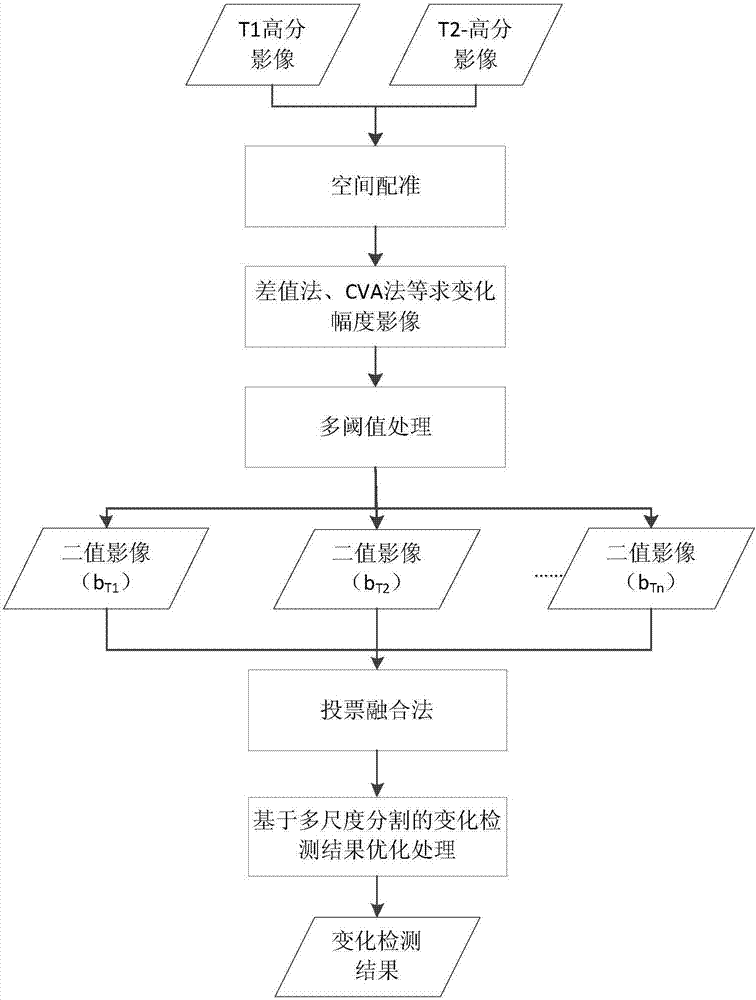
[0047] Specific process such as figure 1 Shown:

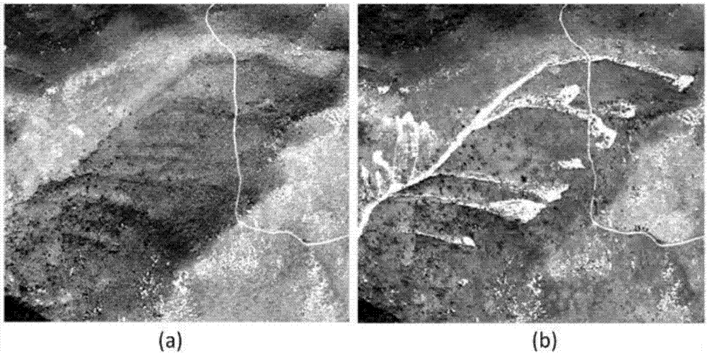
[0048] Step 1. Space registration of two-term images before and after the landslide: before implementation, firstly figure 2 a image before the landslide and figure 2 b The images to be matched were respectively used ArcMap10.0 software, and the geometric registration of the two images was realized by selecting control points and using the Adjust tool.

[0049] Step 2. Solve the variation range image by the difference method. The difference method is the basic method in remote sensing image change detection. The present invention has good generalization. In practical applications, the method for solving the variation range can also use the difference method , CVA method or ratio method and other methods.

[0050] Step 3. Solve the multi-threshold interval: In this example, the minimum range obtained is 0; the maximum change range is 115. If the step size is set to 5, the multi-threshold interval is [5, 159].

[0051] Step...


PUM


Abstract

The invention discloses a non-supervised change detection method based on two-stage high-resolution remote sensing images. The method comprises: step one, spatial position registration is carried out on two-stage remote sensing images in a to-be-detected region before an event and after an event to realize overlapping of geographic areas at a same place; step two, relative changing amplitude images between the two-stage remote sensing images before an event and after an event are calculated; step three, on the basis of the relative changing amplitude images, a multi-threshold zone between a minimum threshold and a maximum threshold is established; step four, with the multi-threshold zone, a plurality of binary changing area detection results are formed by setting an increasing step length S; and step five, fusion processing is carried out on the plurality of binary changing area detection results to obtain an optimized binary changing area detection result. With the non-supervised change detection method, threshold setting is avoided during the process; and the data dependency of the algorithm is reduced.

Description

technical field [0001] The invention belongs to the technical field of remote sensing images, and in particular relates to a non-supervised change detection method based on two-phase high-resolution remote sensing images. Background technique [0002] With the development of remote sensing technology, the spatiotemporal resolution of remote sensing images in the same area has been greatly improved, making it possible to use two remote sensing images to discover areas of land cover change. Using remote sensing images to quickly obtain land cover change areas is of great significance for post-disaster assessment, land use monitoring, and urban expansion monitoring. Change detection based on remote sensing images can be classified into post-classification change detection and pre-classification change detection methods according to the different monitoring results. Among them, the pre-classification change detection method is also called "unsupervised change detection". The pre...

Claims


Application Information

Patent Timeline
IPC IPC(8): G06K9/00
CPCG06V20/13
Inventor 吕志勇张鹏林王映辉
Owner XIAN UNIV OF TECH
Why Eureka
Try Eureka