Double-frequency circular polarization array antenna

An array antenna and circular polarization technology, which is applied in the field of satellite communication, can solve the problems of narrow antenna circular polarization axis ratio bandwidth, large lateral size of feed network, and large single-unit radiation spacing, etc., and achieves compact structure and easy array element Small pitch design, high radiation efficiency

Active Publication Date: 2017-09-29
NO 54 INST OF CHINA ELECTRONICS SCI & TECH GRP
View PDF6 Cites 10 Cited by
  • Summary
  • Abstract
  • Description
  • Claims
  • Application Information

AI Technical Summary

Problems solved by technology

This type of antenna usually uses a pyramidal horn as the radiator, and realizes circularly polarized excitation by means of coaxial probe waveguide cavity perturbation. This method realizes circularly polarized excitation with simple structure and high efficiency, but the feed network The larger the size, the larger the radiation spacing of the single unit, the higher the grating lobe will appear in the high-end pattern of the frequency band during the broadband radiation, resulting in a higher aperture efficiency of the antenna, and the circular polarization axis of this antenna is relatively narrower than the bandwidth, usually in within 10%
[0006] It can be seen that the antennas in the prior art have various disadvantages and have a large room for improvement

Method used


Image

  • Double-frequency circular polarization array antenna
  • Double-frequency circular polarization array antenna
  • Double-frequency circular polarization array antenna

Examples


Embodiment Construction

[0023] In order to make it easier for those skilled in the art to understand the technical solution of this patent, and at the same time, in order to make the technical purpose, technical solution and beneficial effect of this patent clearer, and to fully support the protection scope of the claims, the following is a specific case in the form of this patent. The technical solution of the patent makes further and more detailed descriptions.

[0024] It should be noted that the terms "first" and "second" used in this patent are only text marks used to distinguish multiple / group / category of different objects with the same name, so as to facilitate accurate identification of the technical solution. describe. Apparently, these marker-like terms do not have any sorting or counting meaning, nor do they have the semantic connotation equivalent to articles or demonstrative pronouns.

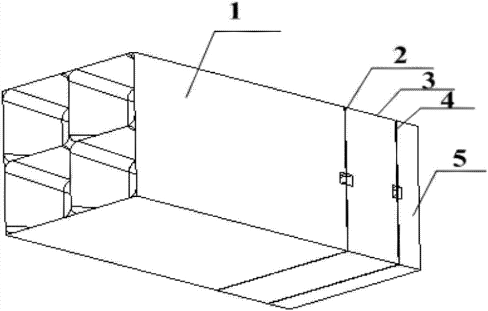
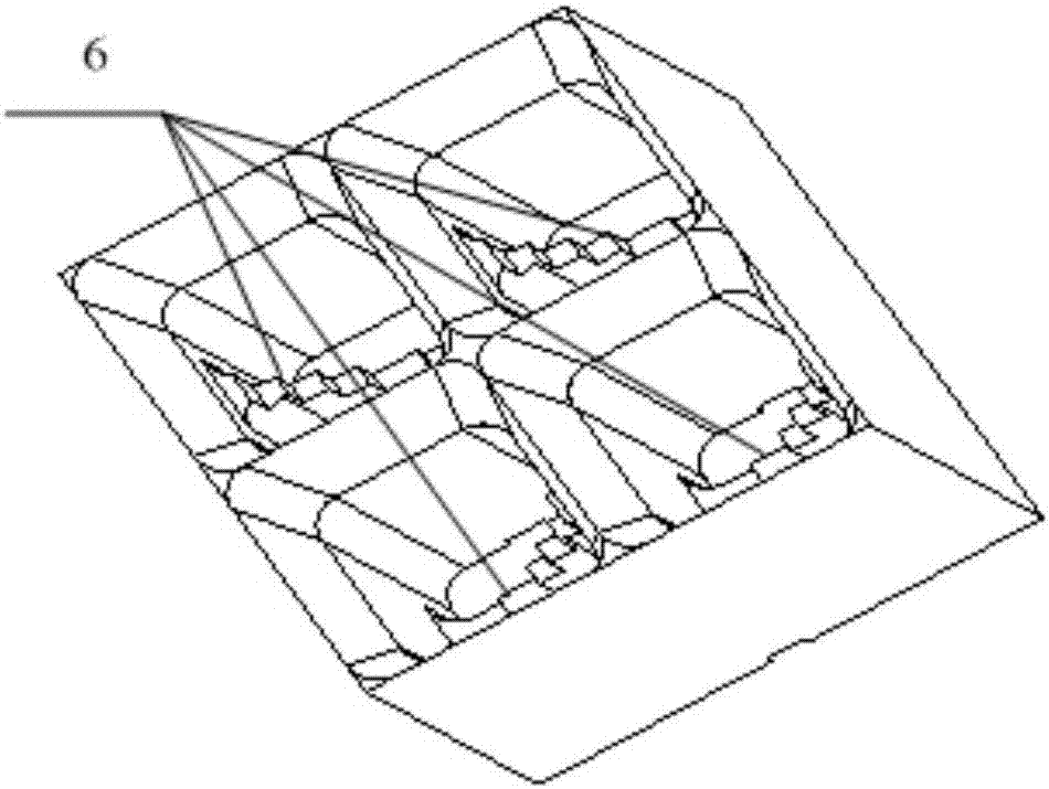
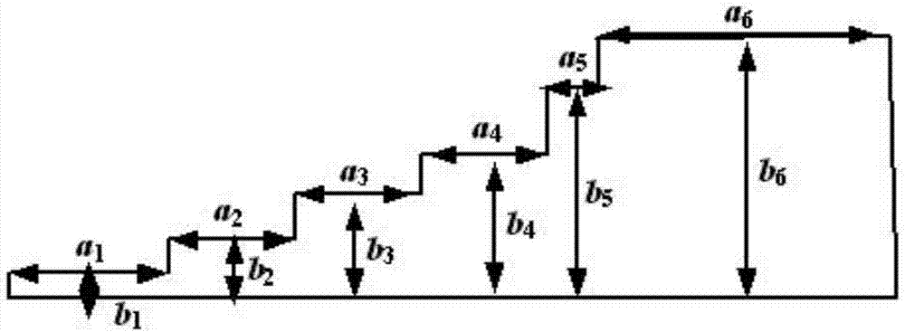
[0025] Such as Figure 1-7 As shown, a dual-frequency circularly polarized array antenna includes a ...


PUM


Abstract

The present invention discloses a double-frequency circular polarization array antenna, belonging to the satellite communication technology field. The antenna comprises four pyramid horns having square calibers and being located at the uppermost portion of the antenna, the pyramid horns are assigned in a 2*2 array mode, the lower portion of each pyramid horn is provided with a waveguide polarizer, the lower portion of each waveguide polarizer is provided with a right-handed polarization feed network, a waveguide transition section, a left-handed polarization feed network and a back cavity layer in order, the upper surface of each waveguide transition section is provided with a first groove, the lower surface of each waveguide transition section is provided with a second groove, the upper surface of each back cavity layer is provided with a third groove being isomorphic to the second groove, the first groove forms the coaxial outer conductor of the right-handed polarization feed network, and the second groove and the third groove form the coaxial outer conductor of the left-handed polarization feed network. The double-frequency circular polarization array antenna is wide in circular polarization axial ratio bandwidth and high in radiation efficiency and can perform dual circular polarization radiation.

Description

technical field [0001] The invention relates to the technical field of satellite communication, in particular to a dual-frequency circularly polarized array antenna. Background technique [0002] At present, in the satellite communication system, the antenna is required to have electrical characteristics such as high gain, high efficiency, and dual polarization. In particular, it is required to have a large interval between the transmitting and receiving frequency bands (about 1.5-2 times the frequency), and circularly polarized radiation. At present, the antennas that achieve the above performance mainly include the following types of antennas, but each has its advantages and disadvantages: [0003] 1. Waveguide slot antenna. This type of antenna is slit on the wide side or narrow side of the waveguide, and usually has two array forms of traveling wave and standing wave, but the gain of the slit of the radiation unit is relatively low, usually only about 7dB. The phenomen...

Claims


Application Information

Patent Timeline
Patent Type & Authority Applications(China)
IPC IPC(8): H01Q21/24H01Q21/00H01Q15/24H01Q13/02H01Q1/50H01Q1/36
CPCH01Q1/36H01Q1/50H01Q13/0241H01Q15/242H01Q21/0006H01Q21/245
Inventor 宋长宏
Owner NO 54 INST OF CHINA ELECTRONICS SCI & TECH GRP
Why Eureka
Try Eureka