Shock absorber with bidirectional pressure limiting piston

A shock absorber and piston technology is applied in the field of shock absorbers with two-way pressure limiting pistons, which can solve the problem that the damping of shock absorbers cannot be further adjusted, and achieve the effect of improving the buffering effect and improving the applicability

Inactive Publication Date: 2017-10-03
王艳
View PDF1 Cites 6 Cited by
  • Summary
  • Abstract
  • Description
  • Claims
  • Application Information

AI Technical Summary

Problems solved by technology

The invention can automatically adjust the size of the damping to ensure the ride comfort and stability of the vehicle. However, the damping force of the invention can only be automatically changed withi

Method used


Image

  • Shock absorber with bidirectional pressure limiting piston
  • Shock absorber with bidirectional pressure limiting piston
  • Shock absorber with bidirectional pressure limiting piston

Examples


Example Embodiment

Specific implementation mode one:

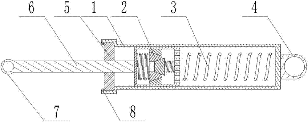
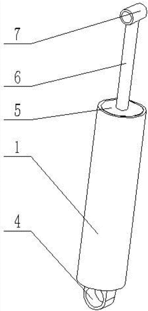
[0030] Combine below Figure 1-9 Describe this embodiment, a shock absorber with a two-way pressure-limiting piston, including a shock-absorbing oil cylinder 1, a two-way pressure-limiting piston 2, a shock-absorbing spring 3, a base suspension ring 4, an oil seal 5, a piston connecting rod 6, and a connecting rod suspension ring 7 and circlip 8, the two-way pressure limiting piston 2 is plugged inside the shock absorbing cylinder 1, a shock absorbing spring 3 is fixedly connected between the shock absorbing cylinder 1 and the two-way pressure limiting piston 2, and the right end of the shock absorbing cylinder 1 is welded to the base The lifting ring 4, the left end of the shock absorbing cylinder 1 is provided with a stepped hole, the oil seal 5 is clamped in the stepped hole, the left end of the stepped hole is provided with a circlip 8, the interior of the shock absorbing cylinder 1 is filled with oil, and the oil seal 5 is used to seal t...

Example Embodiment

Specific implementation mode two:

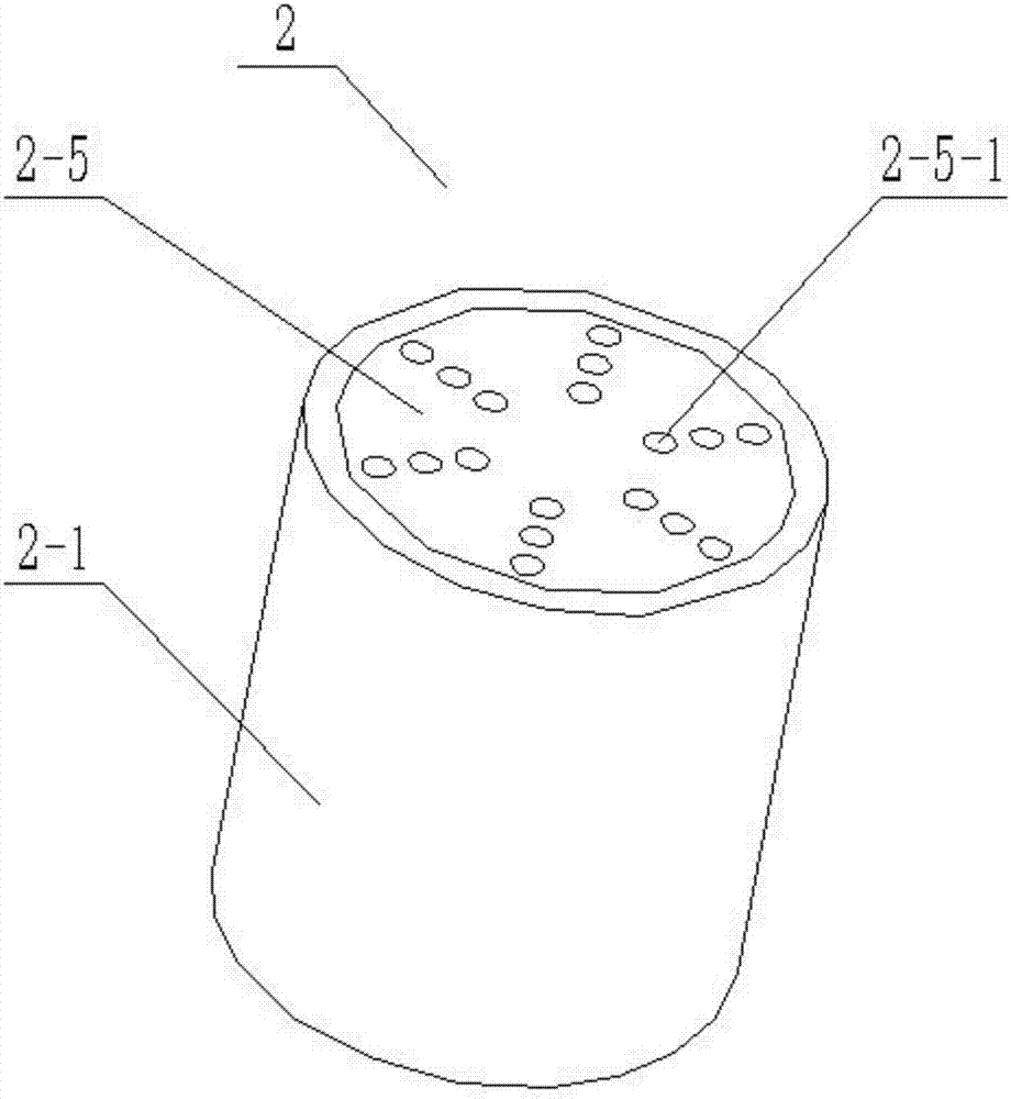
[0031] Combine below Figure 1-9Describe this embodiment, this embodiment will further explain Embodiment 1, the two-way pressure limiting piston 2 includes an outer piston cylinder 2-1, a valve core seat 2-2, a valve core I2-3, a valve core II2-4, a piston The end cover 2-5, the pressure limiting spring I2-6 and the pressure limiting spring II2-7, the outer piston cylinder 2-1 is a cylindrical structure with an open left end and a hollow interior, and the left end of the outer piston cylinder 2-1 is provided with multiple A drain hole I2-1-1, the inner wall of the outer piston cylinder 2-1 is provided with threads, the valve core seat 2-2 is a cylindrical structure, and the valve core seat 2-2 is provided with a valve core hole I2-2 -1, the spool seat 2-2 is coaxial with the spool hole Ⅰ2-2-1, the spool hole Ⅰ2-2-1 is a conical structure with a diameter at the left end larger than that at the right end, and the outer wall of the spool seat ...

Example Embodiment

Specific implementation mode three:

[0032] Combine below Figure 1-9 This embodiment will be described, and this embodiment will further describe the second embodiment, the thread provided on the inner wall of the outer piston cylinder 2-1, the thread provided on the outer wall of the valve core seat 2-2, and the outer wall of the piston end cover 2-5. The threads are all sealed threads, and the position of the valve core seat 2-2 in the outer piston cylinder 2-1 can be adjusted by rotating the valve core seat 2-2, so as to adjust the right end surface of the flow-limiting top column II 2-9 and the outer piston cylinder 2 -1 The distance between the inner right end wall; adjust the distance between the left end face of the flow-limiting top column Ⅰ2-8 and the right end face of the piston end cap 2-5 by rotating the piston end cap 2-5; the sealing thread is used to prevent oil Fluid leaks from threaded connections.


PUM


Abstract

The invention relates to a shock absorber, more specifically a shock absorber with a two-way pressure-limiting piston, including a shock-absorbing oil cylinder, a two-way pressure-limiting piston, a shock-absorbing spring, a base suspension ring, an oil seal, a piston connecting rod and Connecting rod lifting ring, the two-way pressure-limiting piston is plugged inside the shock-absorbing oil cylinder, a shock-absorbing spring is fixedly connected between the shock-absorbing oil cylinder and the two-way pressure-limiting piston, the right end of the shock-absorbing oil cylinder is welded to the base ring, and the left end of the shock-absorbing oil cylinder is provided with a ladder The oil seal is clamped in the stepped hole, the left end of the stepped hole is provided with a circlip, the right end of the piston connecting rod is connected to the two-way pressure limiting piston, and the left end of the piston connecting rod is welded to the connecting rod lifting ring; a pressure reducing piston with a two-way pressure limiting piston The vibrator has the beneficial effects of automatically adjusting the flow velocity of the oil according to the magnitude of the impact force, thereby adjusting the magnitude of the damping effect, and adjusting the range of the oil flow velocity as required.

Description

technical field [0001] The invention relates to a shock absorber, more specifically a shock absorber with a two-way pressure limiting piston. Background technique [0002] The shock absorber is a device used to suppress the shock when the spring rebounds after absorbing the shock and the impact from the road surface. It is widely used in the suspension of the car to accelerate the attenuation of the vibration of the frame and the body to improve the ride comfort of the car. The working principle of the shock absorber is that when the frame and the axle vibrate and there is relative movement, the piston in the shock absorber moves up and down, and the oil in the shock absorber cavity repeatedly flows from one cavity through different pores to another cavity Inside. At this time, the friction between the hole wall and the oil and the internal friction between the oil molecules form a damping force on the vibration, so that the vibration energy of the car is converted into hea...

Claims


Application Information

Patent Timeline
IPC IPC(8): F16F9/18F16F9/32F16F9/34F16F9/512
CPCF16F9/18F16F9/3214F16F9/34F16F9/512
Inventor 王艳
Owner 王艳
Why Eureka
Try Eureka