Deep laser hole linearity detecting device having rotation preventing mechanism

A detection device and straightness technology, applied in measurement devices, optical devices, instruments, etc., can solve the problems of difficult axial positioning of the probe and affect the detection results, and achieve high reliability, high strength, and accurate axial positioning. Effect

Inactive Publication Date: 2017-10-03
ZHONGBEI UNIV
View PDF4 Cites 12 Cited by
  • Summary
  • Abstract
  • Description
  • Claims
  • Application Information

AI Technical Summary

Problems solved by technology

The elasticity of the wire rope will cause the probe to move intermittently in the deep hole instead of the ideal uniform linear motion, which may not only affect the detection results due to vibration, but also make the axial positioning of the probe difficult

Method used


Image

  • Deep laser hole linearity detecting device having rotation preventing mechanism
  • Deep laser hole linearity detecting device having rotation preventing mechanism
  • Deep laser hole linearity detecting device having rotation preventing mechanism

Examples


specific Embodiment approach 1

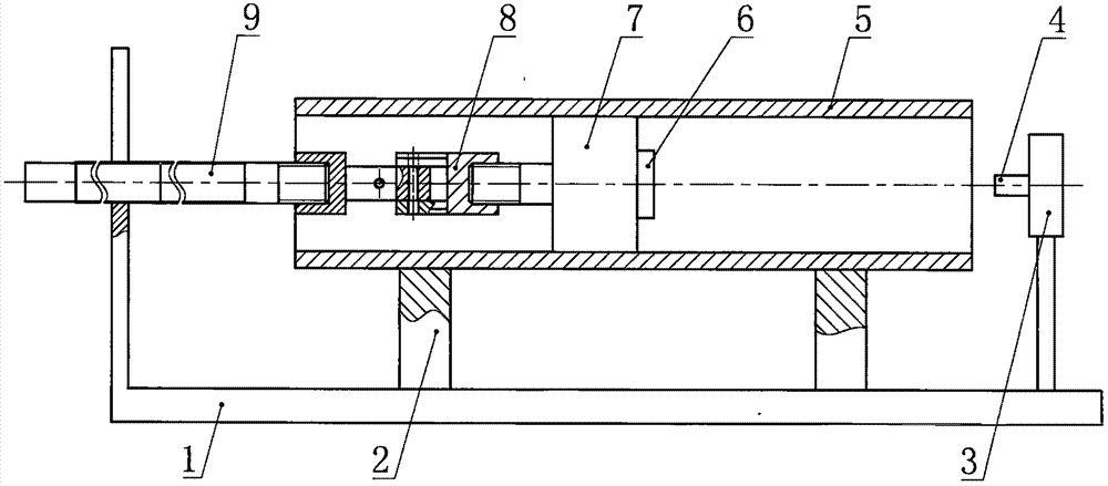
[0024] Two V-shaped blocks 2 are placed on the detection frame 1, the workpiece 5 to be tested is placed on the V-shaped block 2, the PSD sensor 6 is fixed on the probe 7, and the probe 7 is placed in the deep hole. The rigid measuring rod 9 and The measuring head 7 is connected, the laser emitter 4 is fixed on the laser adjustment frame 3 and placed outside the deep hole of the workpiece 5 to be measured, and the antenna is drawn from the PSD sensor 6 in the deep hole to the outside of the deep hole of the workpiece 5 to be measured.

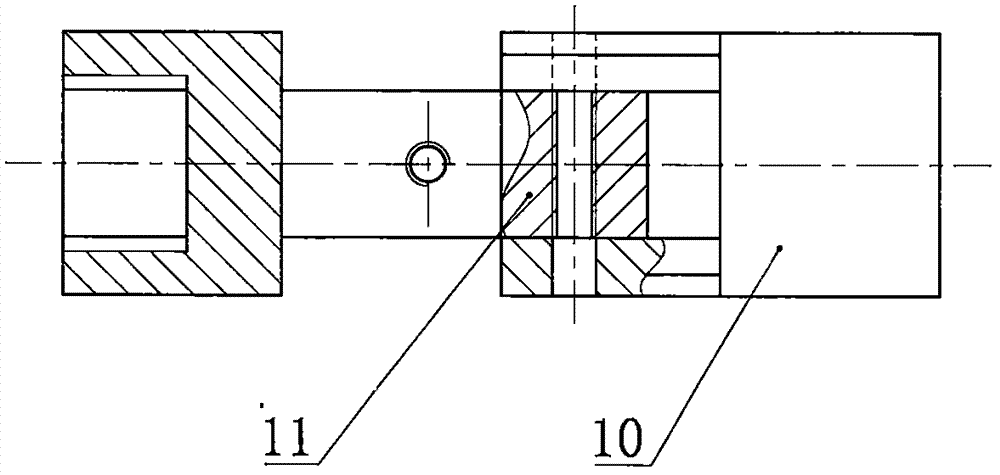
[0025] One end of the universal joint 8 is connected to the measuring head 7, and the other end is connected to the measuring rod 9. The measuring rod 9 is connected by multiple short rods of the same length.

specific Embodiment approach 2

[0026] Two V-shaped blocks 2 are placed on the detection frame 1, the workpiece 5 to be tested is placed on the V-shaped block 2, the PSD sensor 6 is fixed on the probe 7, and the probe 7 is placed in the deep hole. The rigid measuring rod 9 and The measuring head 7 is connected, the laser emitter 4 is fixed on the laser adjustment frame 3 and placed outside the deep hole of the workpiece 5 to be measured, and the antenna is drawn from the PSD sensor 6 in the deep hole to the outside of the deep hole of the workpiece 5 to be measured.

[0027] One end of the universal joint 8 is connected to the measuring head 7, and the other end is connected to the measuring rod 9. The measuring rod 9 is connected by multiple short rods of the same length.


PUM


Abstract

The invention relates to a deep laser hole linearity detecting device having a rotation preventing mechanism. On the basis of the laser alignment principle, a linearity error of an axis of a workpiece hole of a deep hole is measured by using a PSD sensor. A measured workpiece is placed at V-shaped blocks fixed at a detection rack. The PSD sensor is fixed at a measuring head; the measuring head is pulled by a measuring rod to move the PSD sensor from one end of the deep hole to the other end of the deep hole. The measuring rod is a rigid part and multiple segments of the measuring rod are connected to connect the measuring head. In order to prevent rotation of the measuring head around the axis of the deep hole, the measuring rod has a non-circular cross section to realize cooperation with a hole or groove of the detection rack. The measuring rod is connected with the measuring head by a cardan joint to have three translation freedom degrees and have no rotation freedom degree. Detection information is transmitted to the outside of the deep hole by an antenna and the transmitted information is received by a computer. The detecting device has small occupation space; a detection error caused by rotation of the measuring head is eliminated; the antenna extends out of the hole to avoid signal shielding; and the detection precision is high.

Description

technical field [0001] The invention relates to a deep hole straightness detection device, in particular to a laser deep hole straightness detection device with an anti-rotation mechanism. Background technique [0002] In the process of straightness detection of deep holes, the straightness error of deep holes can be obtained more accurately by using PSD sensor with laser detection. However, during the detection process, if the probe is pulled by a flexible wire to move in the deep hole, the probe will rotate at a certain angle around the axis of the deep hole in the deep hole, which will affect the measurement results. Moreover, the flexible cord can only move the measuring head in one direction in the deep hole with pulling force, which is inconvenient for the measuring head to return to the position for multiple measurements, and the efficiency is very low. During the detection process, there is a greater possibility that the wire rope will be broken, which reduces the r...

Claims


Application Information

Patent Timeline
Patent Type & Authority Applications(China)
IPC IPC(8): G01B11/27
CPCG01B11/27
Inventor 于大国
Owner ZHONGBEI UNIV
Why Eureka
Try Eureka