

Drive hub bearing unit spin riveting pressure measurement system and measurement method
A wheel hub bearing and measurement method technology, applied in force/torque/work measuring instrument, measuring force, measuring device, etc., can solve problems such as uncertain axial preload effect, fracture of flange shaft, affecting driving safety, etc. Achieve the effects of reasonable structural design, guaranteed safety, and simple measurement methods
- Summary
- Abstract
- Description
- Claims
- Application Information
AI Technical Summary
Problems solved by technology
Method used
Image

Examples
Embodiment 1
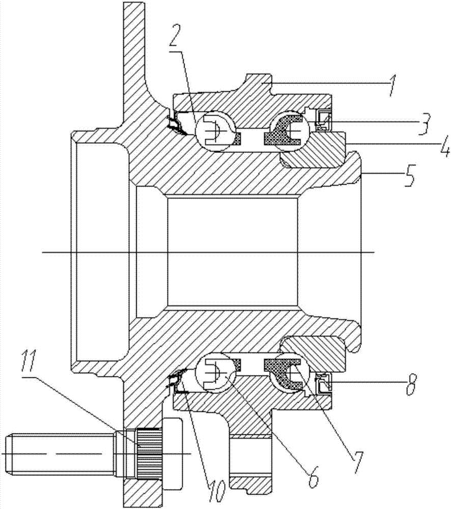
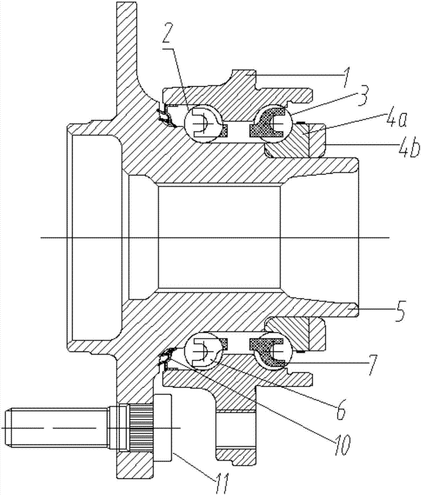
[0036] Such as Figure 2 to Figure 3 As shown in the figure, a driving hub bearing unit spin riveting pressure measurement system includes an outer ring 1, an outer row of steel balls 2, an inner row of steel balls 3, a flange 5, an outer cage 6, an inner cage 7, bolts 11 and Strain gauge 9, the drive hub bearing unit is provided with an inner ring 4; part of the structure of the inner ring 4 is cut and polished to form a strain ring 4a and a spin riveting ring 4b, and the strain ring 4a is matched with the journal of the flange 5 with a clearance of 0.040mm, the use of this fit gap can prevent the circumferential strain effect caused by the interference fit between the strain ring 4a and the flange 5 journal, and also avoid the reduction of the axial guiding effect due to the excessive gap; the spin riveting ring 4b Interference fit with the flange plate 5; the small end surface of the strain ring 4a and the small end surface of the spin riveting ring 4b fit each other; the n...
Embodiment 2
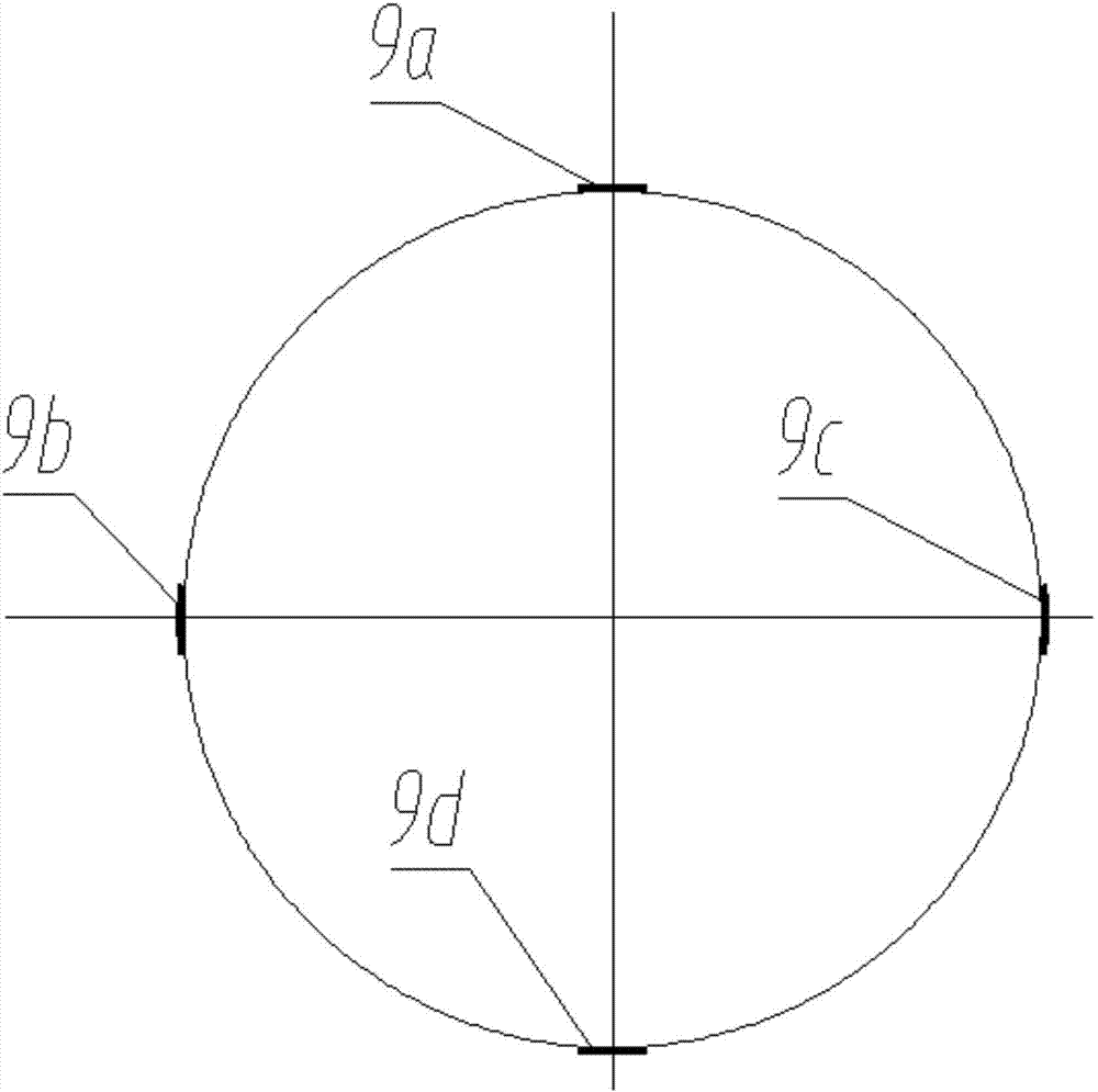
[0050] As in embodiment 1, the only difference is that there is only one strain gauge 9, which is pasted on the outer diameter of the strain ring 4a, the axial positioning is consistent with that of embodiment 1, and the circumferential positioning is randomly arranged in the 360-degree circumferential direction.
[0051] A method for measuring the rivet pressure of a drive hub bearing unit, comprising the following steps:
[0052] A. Parts preparation, part of the structure of the inner ring 4 of the drive hub bearing unit is cut and polished to form a strain ring 4a and a spin riveting ring 4b; the strain ring 4a and the journal of the flange 5 are clearance fit, and the fit clearance is 0.042mm; An interference fit of 0.024mm is maintained between the riveting ring 4b and the flange 5; a strain gauge 9 is pasted on the outer diameter of the strain ring 4a;
[0053] B. Parts matching, after assembling the outer ring 1, the outer row of steel balls 2, the inner row of steel b...
PUM
 Abstract
Description
Claims
Application Information