

Method of evaluating glass substrate heat shrinkage
A glass substrate, thermal shrinkage technology, applied in the direction of material thermal expansion coefficient, measuring device, instrument, etc., can solve the problem of not measuring the thermal shrinkage of the whole board, uneven thermal shrinkage, etc., achieve good application prospects, simplify the evaluation process, shorten the evaluation process effect of time
- Summary
- Abstract
- Description
- Claims
- Application Information
AI Technical Summary
Problems solved by technology
Method used
Image


Examples
Embodiment 1
[0087] This example is used to illustrate the method for evaluating thermal shrinkage of a glass substrate provided by the present invention.
[0088] (1) Preparation of the bottom plate
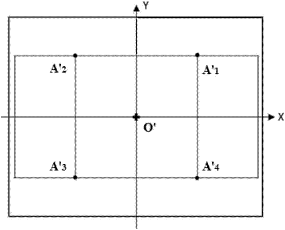
[0089] According to the size of the glass substrate to be tested (TFT-LCD G4 0.5mm glass substrate, purchased from Corning, size 830mm×650mm), prepare a rectangular bottom plate that is larger than the glass substrate and made of plastic, and mark the center of the bottom plate with a laser dotting instrument The origin O' in the form of a cross, and then use the laser scriber to calibrate the mutually perpendicular X-axis and Y-axis through the origin O', and divide the strip-tested glass substrate into four areas, where the X-axis is parallel to the long side of the bottom plate, And divide the X axis and Y axis into equal parts respectively to form a grid on the base plate. The grid is rectangular, its length and width are both 200mm, and an intersection point of the grid is used as the ...
Embodiment 2
[0108] This example is used to illustrate the method for evaluating shrinkage of a glass substrate provided by the present invention.
[0109] Carry out according to the method for embodiment 1, the difference is that the glass substrate to be tested is a TFT-LCD G6 0.4mm glass substrate (purchased from Corning Corporation, size 1800mm * 1500mm), and correspondingly select the glass substrate with a size larger than the glass substrate to be tested. Plastic bottom plate; in step (1), grid is rectangular, and its length is 500mm, and width is 300mm; Raise the temperature to 400°C, keep it warm for 40s, then cool down to 250°C at a cooling rate of 50°C / min, and air-cool to room temperature (25°C).
[0110] Mark a coordinate point in each of the four areas of the base plate (respectively A’ 5 、A' 6 、A' 7 and A' 8 ), respectively corresponding to four test points on the glass substrate to be tested (respectively A 5 、A 6 、A 7 and A 8 ), according to the above method and ca...
Embodiment 3
[0114] This example is used to illustrate the method for evaluating shrinkage of a glass substrate provided by the present invention.
[0115] Carry out according to the method of embodiment 1, the difference is that the glass substrate to be tested is a TFT-LCD G8.5 0.5mm glass substrate (purchased from Corning, size 2500mm × 2200mm), and the corresponding size is selected to be larger than the glass to be tested. The plastic bottom plate of substrate; In step (1), grid is rectangular, and its length is 500mm, and width is 400mm; In step (2), the condition of heat treatment is: with the heating rate of 50 ℃ / min, by room temperature ( 25°C) to 600°C, keep the temperature for 60s, then cool down to 250°C at a cooling rate of 60°C / min, and air cool to room temperature (25°C).
[0116] Mark a coordinate point in each of the four areas of the base plate (respectively A’ 9 、A' 10 、A' 11 and A' 12 ), respectively corresponding to the four points to be measured on the glass subst...
PUM
 Abstract
Description
Claims
Application Information