On-orbit SAR image change detection method based on sample self-calibration elm

An image change detection and change detection technology, which is applied in image analysis, image enhancement, image data processing and other directions, can solve the problem that the detection accuracy and robustness of the on-orbit SAR image change detection method are not ideal, the resolution of detection results and the imaging method. Instability, inability to flexibly apply different imaging methods, etc., to achieve the effects of excellent calculation results, improved detection quality, and fast calculation speed

Active Publication Date: 2020-11-03
XIDIAN UNIV
View PDF4 Cites 0 Cited by
  • Summary
  • Abstract
  • Description
  • Claims
  • Application Information

AI Technical Summary

Problems solved by technology

Although the detection method based on this idea eliminates the need for on-board network parameter training and improves the speed of the detection method to a certain extent, due to the scarcity and high cost of training data information and the network parameters of the on-board detection method fixed, so that when such methods are faced with data of target areas with different widths, different resolutions, and different imaging methods, their detection quality is subject to great fluctuations. Stability, which severely limits the practical application of the detection method
[0005] In summary, the detection accuracy and robustness of the unsupervised on-orbit SAR image change detection method are not ideal; the supervised on-orbit SAR image change detection method requires manual labeling of the training data, which cannot be flexibly applied to different imaging methods , the detection results are unstable due to different resolutions and imaging methods

Method used


Image

  • On-orbit SAR image change detection method based on sample self-calibration elm
  • On-orbit SAR image change detection method based on sample self-calibration elm
  • On-orbit SAR image change detection method based on sample self-calibration elm

Examples


Embodiment 1

[0029] The supervised on-orbit SAR image change detection method is limited by a large amount of manually labeled data, and the method of using ground training data and on-board detection cannot be stably applied to SAR image data of different imaging methods and resolutions. Aiming at this current situation, the present invention explores and improves, and proposes an on-orbit SAR image change detection method based on sample self-calibration ELM.

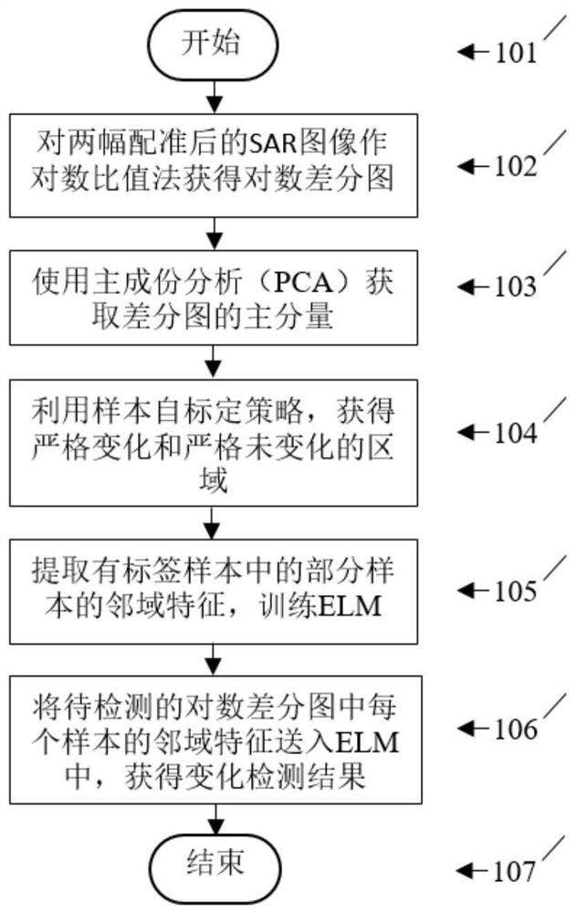
[0030] see figure 1 : the present invention directly carries out change detection to the registered SAR image on the satellite, specifically comprising the following steps:

[0031] Step 101: Start the on-orbit change detection based on the sample self-calibration ELM.

[0032] Step 102: Pair X of the two registered SAR images of the same area but different time phases taken from the radar 1 and x 2 , where image X 1 Indicates the SAR image of the first phase of the same area, X 2 SAR image representing the second phase of th...

Embodiment 2

[0040] The overall technical solution of the on-orbit SAR image change detection method based on the sample self-calibration ELM is the same as that in Embodiment 1, and the logarithmic ratio method calculation in step 102 of the present invention includes the following steps:

[0041] Step 201: Start the logarithmic ratio calculation.

[0042] Step 202: pair the two registered SAR images of the same area but different time phases taken from the radar to X 1 and x 2 The logarithmic difference graph DI is generated according to the following formula:

[0043]

[0044] Where ε is a very small normal number, and the range of values ​​is generally [10 -4 , 10 0 ];X 1 Indicates the SAR image of the target area before the change, X 2 Indicates the SAR image of the target area after the change.

[0045] Step 203: Normalize the generated logarithmic difference map DI, expressed as:

[0046]

[0047] where DI max and DI min Represent the maximum and minimum values ​​of t...

Embodiment 3

[0050] The overall technical solution of the on-orbit SAR image change detection method based on the sample self-calibration ELM is the same as that of embodiment 1-2, and the principal component of the normalized logarithmic difference map obtained in step 103 includes the following steps:

[0051] Step 301: Start to use principal component analysis (PCA) to extract the principal components of the normalized logarithmic difference graph.

[0052] Step 302: Divide the normalized logarithmic difference image into several non-overlapping image blocks, the size of each image block is k×k, and the size of the image block is set to 5×5 in this example.

[0053] Step 303: pull all the segmented image blocks into a column vector, and call PCA to retain 99% of its information.

[0054] Step 304: Restore the blocks drawn into column vectors to obtain the principal components of the normalized logarithmic difference map.

[0055] Step 305: Finish using principal component analysis (PCA...


PUM


Abstract

The invention proposes an on-orbit SAR image change detection method based on the sample self-calibration ELM, which improves the detection accuracy and expands the practical application range of the method. The steps include: calculating and obtaining the logarithmic difference map DI for two SAR image pairs of the registration phase; using PCA to obtain the principal component of DI; using the sample self-calibration strategy to obtain the strict change of the principal component of the logarithmic difference map after normalization region and strictly unchanged region; extract the neighborhood features of some samples from it, and use it as a training sample to train ELM; send the neighborhood of each sample in the logarithmic difference map to be detected to the trained ELM to obtain change detection Result graph. The present invention automatically extracts training samples from the differential image to be detected, eliminates the limitation of the training data on the detection ability of the method, expands the practical application range of the method, avoids manual participation, reduces the interference of noise, and improves the detection accuracy of the method rate, with stable and reliable detection capabilities.

Description

technical field [0001] The invention belongs to the technical field of image detection, and mainly relates to SAR image change detection, in particular to an on-orbit SAR image change detection method based on sample self-calibration ELM. It is used for real-time on-orbit change detection of SAR images captured by satellites. Background technique [0002] Synthetic Aperture Radar (SAR) is a high-resolution imaging radar that can obtain high-resolution radar images similar to optical photography in weather conditions with extremely low visibility. Due to its excellent characteristics, SAR has been widely used in industrial and agricultural production, urban monitoring, military and scientific research and other fields. SAR-based image change detection is to compare and analyze two images of the same area at different times, identify the differences between the images, and obtain the required target or terrain change information. Nowadays, with the rapid development of citie...

Claims


Application Information

Patent Timeline
Patent Type & Authority Patents(China)
IPC IPC(8): G06T7/00G06K9/62G06N3/04G06N3/08
CPCG06N3/04G06N3/08G06T7/0002G06T2207/30181G06T2207/20224G06T2207/10044G06T2207/20081G06T2207/20084G06F18/2321
Inventor 杨淑媛焦李成李剑马晶晶刘志李倩兰马宏斌邢颖慧冯志玺张凯王士刚
Owner XIDIAN UNIV
Why Eureka
Try Eureka