Metal foil piece type current detection resistor and manufacturing process thereof

A technology of current detection resistors and manufacturing process, which is applied in the direction of non-adjustable metal resistors, resistors, and resistor manufacturing. It can solve the problems of reduced power resistance of resistors, large temperature coefficient of resistors, and long heat dissipation paths, etc., to improve power. , to ensure integrity, to improve the effect of the temperature coefficient index

Active Publication Date: 2017-10-03
UNIROYAL ELECTRONICS IND
View PDF10 Cites 6 Cited by
  • Summary
  • Abstract
  • Description
  • Claims
  • Application Information

AI Technical Summary

Problems solved by technology

[0003] First, the resistance layer is close to the center of the insulating substrate and far away from the side electrodes. The heat of the resistance is often gathered in the middle of the resistance layer, and the heat of the resistance is dissipated from the middle to the electrodes at both ends and the side electrodes. The problem of poor heat dissipation caused by too long path
[0004] Second, when ordinary low-resistance resistors are corrected by laser resistance, no matter whether single-knife cutting or count

Method used


Image

  • Metal foil piece type current detection resistor and manufacturing process thereof
  • Metal foil piece type current detection resistor and manufacturing process thereof
  • Metal foil piece type current detection resistor and manufacturing process thereof

Examples


Embodiment 1

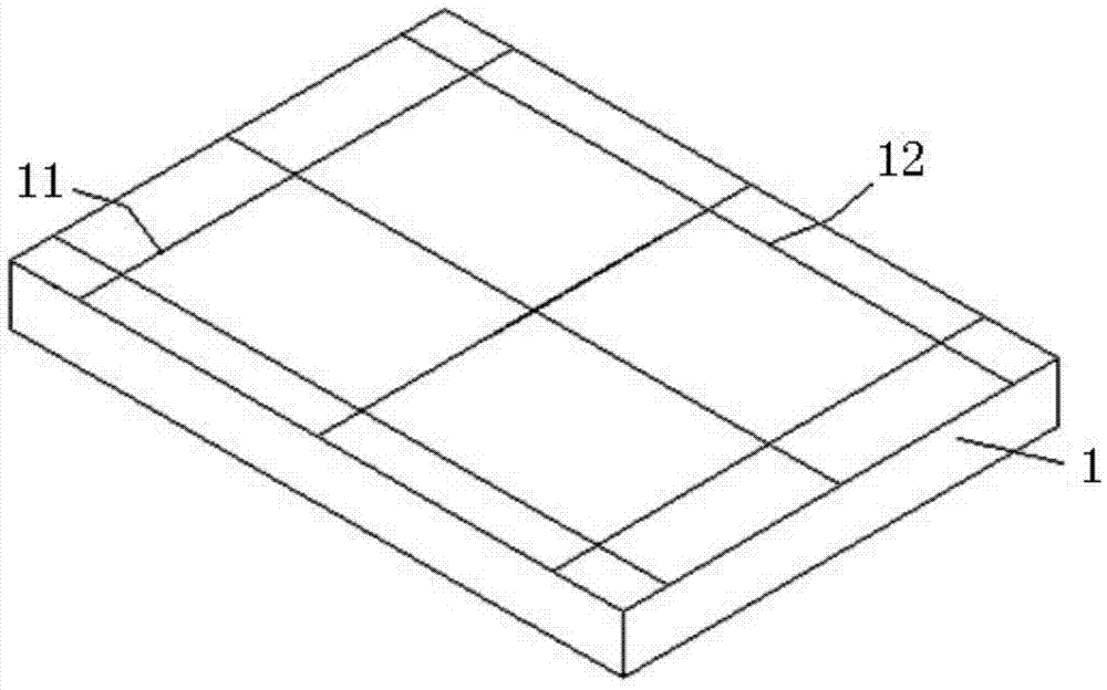
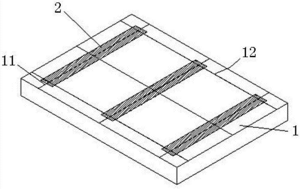
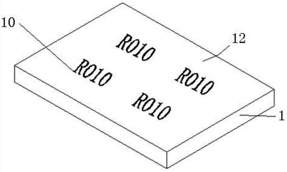
[0060] Embodiment 1: see attached Figure 15 and 16 As shown, a metal foil current detection resistor includes a square block insulating substrate 1, the insulating substrate 1 has a front side and a back side, wherein a product logo 10 is printed in the center on the front side of the insulating substrate 1, and the logo The material is resin paste, and front electrodes 3 are symmetrically printed by screen printing on both sides of the front side of the insulating substrate 1 extending along the X-axis direction (ie, the width direction), and the electrode material of the front electrode is resin paste; On the back of the insulating substrate 1 and on both sides extending along the X-axis direction, there are back electrodes 2 symmetrically printed by screen printing. The electrode material of the back electrodes is resin paste, and the back electrodes on the back of the insulating substrate are 2 also correspond to the front electrodes 3 on the front side of the insulating...


PUM


Abstract

The invention discloses a metal foil chip type current detection resistor and a manufacturing process thereof. Front electrodes are symmetrically printed on two sides, extending along the x-axis direction, of the front surface of the insulating substrate, and back electrodes are symmetrically printed on two sides, extending along the x-axis direction, of the back surface of the insulating substrate, the back electrodes and the front electrodes are in one-to-one correspondence and are symmetrically arranged, so that the electrodes at the two ends of the insulating substrate are full, the resistance integrity is guaranteed, and the power of the chip fixed resistor is improved. The R part of the resistor is made of the alloy foil, so that the resistance value can be ensured, and the stability of the resistance value can be ensured, and an excellent resistor temperature coefficient index can be achieved; in addition, the R part of the resistor is arranged on the back surface of the insulating substrate, the heat dissipation path and the heat dissipation condition can be greatly improved, and the resistor can quickly dissipate the heat of the resistor to the PCB. It is guaranteed that the power of the chip fixed resistor is further improved. The metal foil type current detection resistor can be widely applied to manufacturing of a power supply.

Description

technical field [0001] The invention relates to the technical field of resistors, and specifically provides a metal foil type current detection resistor and a manufacturing process thereof. Background technique [0002] With the advancement of science and technology, the development of the times, and the continuous improvement of people's requirements for the miniaturization of electronic products, thick film chip resistors with reliable performance and stable process are also showing a diversified development trend in response to the characteristics of electronic products. As we all know, In order to ensure the stable operation of various electronic products, a power supply will be produced to ensure its normal and stable operation, and the stable operation of each power supply is inseparable from a low voltage sensor connected to the feedback circuit for current detection. Resistance resistor, this kind of resistor is the current detection resistor that people often talk a...

Claims


Application Information

Patent Timeline
IPC IPC(8): H01C1/04H01C1/084H01C1/142H01C3/00H01C17/00H01C17/242H01C17/28H01C17/30
CPCH01C1/04H01C1/084H01C1/142H01C3/00H01C17/003H01C17/242H01C17/281H01C17/30
Inventor 张军会王腾毅吴术爱廖冬梅陈玲金号春
Owner UNIROYAL ELECTRONICS IND
Why Eureka
Try Eureka