Punching machine of medicine bottle caps

A cap stamping machine and medicine bottle technology, applied in capping, feeding device, positioning device, etc., can solve the problems of reducing production efficiency, increasing cutting steps, not easy to control, etc., achieving simple structure, improving utilization rate, and saving The effect of raw materials

Inactive Publication Date: 2017-10-10
浙江冠利新材料股份有限公司
View PDF8 Cites 2 Cited by
  • Summary
  • Abstract
  • Description
  • Claims
  • Application Information

AI Technical Summary

Problems solved by technology

What is used in this production step is a stamping machine for cutting the plate body. The stamping machine mainly includes a stamping mechanism and a feeding mechanism, while the traditional stamping machine has the following shortcomings: 1. The stamping mechanism mainly adopts hydraulic stamping The method requires the hydraulic oil circuit to control the output frequency of the hydraulic cylinder (that is, the stamping frequency), the structure is too complicated and not easy to control; and the workpiece obtained by stamping is easy to be adsorbed on the stamping head, resulting in unsmooth blanking and unable to guarantee product quality
2. The blanking mechanism of the existing punching machine needs to cooperate with the punching frequency of the punching machine to do telescopic feeding to the punching station. In this way, it is necessary to ensure the coordination of the actions between the blanking mechanism and the punching mechanism. Such a structure is too complicated and urgently needed Improve
3. The feeding mechanism can only feed in one direction, so it is necessary to cut the purchased raw material board into strips longitudinally, and then fix the strip-shaped raw material board on the feeding mechanism for transportation; this increases the cutting steps and reduces the production efficiency ; and because the stamping plate for making the coil shell is a circular steel plate, the feeding mechanism can only feed in one direction, so it is impossible to reasonably distribute the stamping area of ​​the raw material plate, and only the strip-shaped raw material plate can be stamped and cut, resulting in great waste of material

Method used


Image

  • Punching machine of medicine bottle caps
  • Punching machine of medicine bottle caps
  • Punching machine of medicine bottle caps

Examples


Embodiment Construction

[0019] The preferred embodiments of the present invention will be described in further detail below in conjunction with the accompanying drawings.

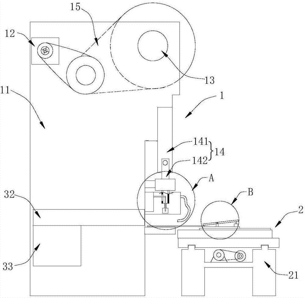
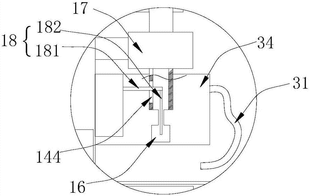
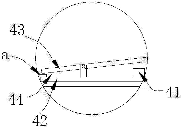
[0020] Such as Figure 1~4 A stamping machine for medicine bottle caps shown includes a stamping mechanism 1, a feeding mechanism 2 and a blanking mechanism.

[0021] The punching mechanism 1 includes a frame 11 , and a punching motor 12 , an eccentric shaft 13 and a punching shaft 14 arranged on the frame 11 . Both ends of the eccentric shaft 13 are positioned on the frame 11 through bearings, and the output end of the stamping motor 12 is connected to the eccentric shaft 13 through a transmission assembly 15, which can be a transmission wheel belt assembly as shown in the figure. The punching shaft 14 is longitudinally slidably positioned on the frame 11, the upper end of the punching shaft 14 is sleeved on the eccentric shaft 13, and the lower end of the punching shaft 14 is provided with a punching die 16 for cutting raw mate...


PUM


Abstract

The invention relates to the field of bottle cap processing equipment, in particular to a punching machine of medicine bottle caps. The punching machine of the medicine bottle caps comprises a punching mechanism, a feeding mechanism and a discharging mechanism. The punching mechanism comprises a rack, a punching motor, an eccentric shaft and a punching shaft, wherein the punching motor, the eccentric shaft and the punching shaft are arranged on the rack; the two ends of the eccentric shaft are positioned on the rack through bearings, and the output end of the punching motor is in transmission connection with the eccentric shaft through a transmission assembly; and the punching shaft is longitudinally and slidably positioned on the rack, the upper end of the punching shaft is connected on the eccentric shaft in a sleeving mode, a punching die used for cutting plate bodies of raw materials is arranged at the lower end of the punching shaft, and the punching die is located above the feeding mechanism. According to the punching machine of the medicine bottle caps, the structure is simple and practical, and equipment operation is stable.

Description

technical field [0001] The invention relates to the field of bottle cap processing equipment, in particular to a punching machine for medicine bottle caps. Background technique [0002] Aluminum metal bottle cap is a kind of commonly used medicine bottle cap. The first step in the production process of this kind of metal bottle cap is: stamping and pressing the raw material plate, that is, cutting it from the raw material plate to make the medicine bottle cap The raw material plate is pressed into the basic shape of the medicine bottle cap while stamping. What is used in this production step is a stamping machine for cutting the plate body. The stamping machine mainly includes a stamping mechanism and a feeding mechanism, while the traditional stamping machine has the following shortcomings: 1. The stamping mechanism mainly adopts hydraulic stamping The method requires the hydraulic oil circuit to control the output frequency of the hydraulic cylinder (that is, the stamping...

Claims


Application Information

Patent Timeline
Patent Type & Authority Applications(China)
IPC IPC(8): B21D28/02B21D51/48B21D45/02B21D45/00B21D43/11B21D43/13
CPCB21D28/02B21D43/11B21D43/13B21D45/00B21D45/02B21D51/48
Inventor 陈国伟姚卫峰
Owner 浙江冠利新材料股份有限公司
Why Eureka
Try Eureka