Hydraulic driving device

A driving device and hydraulic technology, applied in the direction of manipulators, manufacturing tools, etc., can solve the problems of flexible and bionic driving that cannot be applied to robots, and achieve the effect of reducing the overall structural weight, various structural designs, and small volume.

Pending Publication Date: 2017-10-10
葛广徽
View PDF6 Cites 2 Cited by
  • Summary
  • Abstract
  • Description
  • Claims
  • Application Information

AI Technical Summary

Problems solved by technology

[0006] In view of the above problems, the present invention provides a hydraulic driving device, which changes the liquid volume in the cyst cavity through the hydraulic system, and changes the shape of the cyst cavity by the external pressure to complete the swing and other actions, which can effectively solve the problem that the existing driving device cannot be applied to bionic applications. Flexible biomimetic actuation of fish, mollusks, or robots, and control of finger grip forces for humanoid robots

Method used


Image

  • Hydraulic driving device
  • Hydraulic driving device
  • Hydraulic driving device

Examples


Embodiment 1

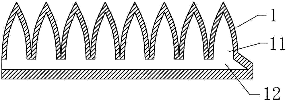
[0039] Refer to attached figure 1 , a unilateral hydraulic drive device, including a sac-shaped bending structure 1 and a hydraulic drive pump 2 arranged on one side, which changes the liquid volume in the sac cavity through the hydraulic drive system, and changes the shape of the sac cavity by the external pressure to complete actions such as rocking .

[0040] The above-mentioned sac-shaped curved structure 1 includes a liquid sac 11 and an integral through-type liquid channel 12 connecting multiple liquid sacs 11, wherein the cross-section of the liquid sac 11 is in the shape of scales, and the left end of the liquid channel 12 is the water inlet and outlet end, which is used to connect the hydraulic drive pump 2 It is used to fill or extract liquid, and the other end is sealed.

[0041] The capsule-shaped curved structure 1 is specifically made of flexible silicone material.

Embodiment 2

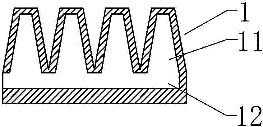
[0043] Refer to attached figure 2 , a unilateral hydraulic drive device, including a sac-shaped bending structure 1 and a hydraulic drive pump 2 arranged on one side, which changes the liquid volume in the sac cavity through the hydraulic drive system, and changes the shape of the sac cavity by the external pressure to complete actions such as rocking .

[0044] The above-mentioned sac-like curved structure 1 includes a liquid sac 11 and a liquid channel 12 connecting multiple liquid sacs 11, wherein the section of the liquid sac 11 is trapezoidal in shape, the height of the liquid sac 11 can be flexible depending on the specific situation, and the left end of the liquid channel 12 is connected to a hydraulic drive. The other end of the pump 2 is sealed, and the liquid channel 12 is closely connected with the hydraulically driven pump 2 in any manner.

Embodiment 3

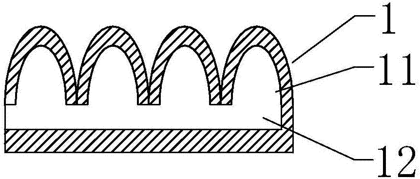
[0046] Refer to attached image 3 , a unilateral hydraulic drive device, including a bladder-like curved structure 1 and a hydraulic drive pump 2 .

[0047] The above-mentioned sac-like curved structure 1 includes a liquid sac 11 and a liquid channel 12 connecting multiple liquid sacs 11, wherein the section of the liquid sac 11 is semi-elliptical, the height of the liquid sac 11 can be flexible depending on the specific situation, and the left end of the liquid channel 12 is connected to the hydraulic pressure. The drive pump 2 is sealed at the other end, and the liquid channel 12 is tightly connected with the hydraulic drive pump 2 through threads and a rubber sealing structure.


PUM


Abstract

The invention discloses a hydraulic driving device which comprises one or more bag-shaped bent structures and a hydraulic driving pump. Each bag-shaped bent structure comprises one or more liquid bags and a liquid channel communicating with the liquid bags. The bag opening end is longer than the sealed end of the longitudinal section of each liquid bag. One end of the liquid channel is connected with the hydraulic driving pump and used for sucking or extracting liquid, and the other end of the liquid channel is sealed. Compared with a metal hydraulic driving device, the overall structure weight is reduced, and the hydraulic driving device can be conveniently applied to a small robot. Compared with a pneumatic mechanical grip, the size is smaller, the device can be conveniently applied to the small robot, meanwhile, the moving ways can be adjusted in various gears, structural design is various, the moving postures of various organisms can be flexibly and accurately simulated as needed, and the best solution for simulating biomimetic motion is achieved while electric control deformation materials are not mature at present.

Description

technical field [0001] The invention relates to a driving structure, in particular to a flexible hydraulic driving device which can be applied in various bionic driving structures. Background technique [0002] Traditional rigid hydraulic devices generally carry out mechanical transmission through cylinder pressurization. Most of these driving devices have thick metal casings, which make them heavy and unsuitable for use on small robots. [0003] There is also a pneumatic industrial robot gripper, which uses a pneumatic structure driving device to realize swing. [0004] For example, the patent document with the authorized notification number CN 104227721 B discloses a variable stiffness module of a bionic soft robot, the variable stiffness module includes an elastic base, a ventilator, a central drive cavity and a side drive cavity, the elastic base The cross section is circular, and the middle part of the elastic matrix is ​​provided with a central driving chamber, and a...

Claims


Application Information

Patent Timeline
Patent Type & Authority Applications(China)
IPC IPC(8): B25J19/00B25J11/00
CPCB25J11/00B25J19/00
Inventor 葛广徽
Owner 葛广徽
Why Eureka
Try Eureka