Construction method of beam body structure

A construction method and beam body technology, applied to bridges, bridge construction, erection/assembly of bridges, etc., can solve the problems of large construction volume, difficulty in dismantling, and low economic efficiency, and achieve easy hoisting construction, low material consumption, and easy construction. short cycle effect

Inactive Publication Date: 2017-10-10
CCCC SECOND HARBOR ENG
View PDF6 Cites 8 Cited by
  • Summary
  • Abstract
  • Description
  • Claims
  • Application Information

AI Technical Summary

Problems solved by technology

This construction method is suitable for the situation where the traffic under the bridge can be closed or the requirement for the clearance under the bridge is not high, and the construction period is not tight. The design and construction methods will show corresponding shortcomings
Image 6 The beam structure shown is the existing pouring construction. If the entire span beam structure is prefabricated and hoisted at one time, large hoisting equipment is required, and the economy is not high
If the formwork cast-in-place construction method is adopted, it is necessary to set up the base form and the side formwork on the pier column for one-time pouring construction, which requires a large amount of construction and will occupy the space under the bridge for a long time to support the formwork. Large amount and difficult to dismantle

Method used


Image

  • Construction method of beam body structure
  • Construction method of beam body structure
  • Construction method of beam body structure

Examples


Embodiment Construction

[0024] The present invention will be further described in detail below in conjunction with the accompanying drawings and specific embodiments.

[0025] Such as figure 1 The construction method of the beam body structure shown in -5 comprises the following steps:

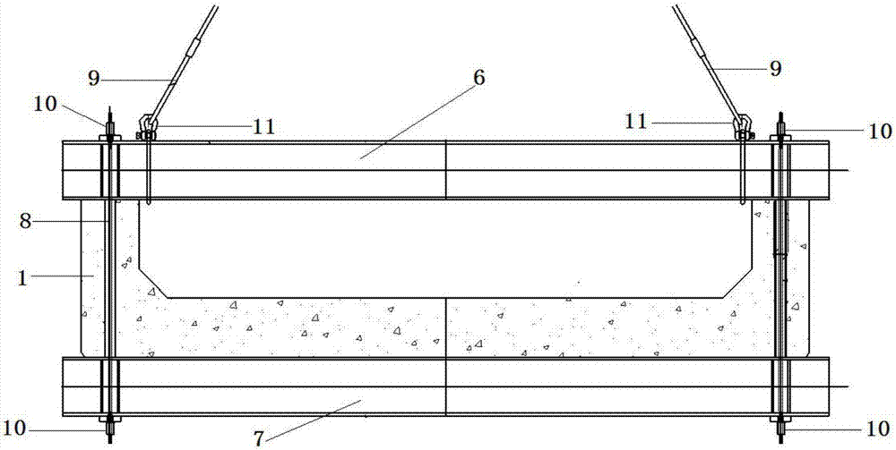
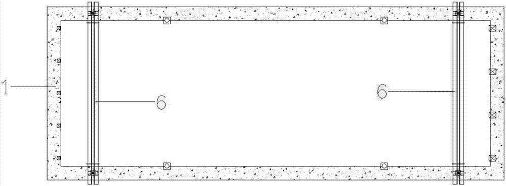
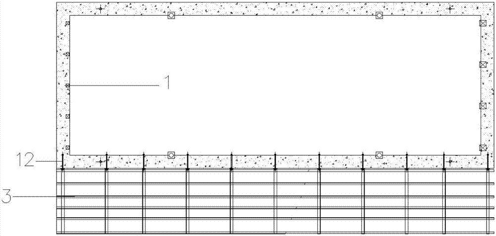
[0026] 1) Based on the cross-section of the beam structure, the beam structure is divided into U-shaped base 1, the upper reinforced concrete 4 arranged in the U-shaped groove of U-shaped base 1, and the left and right sides of U-shaped base 1. The flange plate 5 has three parts;

[0027] 2), prefabricated U-shaped base 1, a group of hoisting brackets are respectively arranged on the front and rear sides of U-shaped base 1, and each group of hoisting brackets includes a hoisting upper beam 6 located on the top surface of U-shaped base 1 and a hoisting upper beam 6 located on the bottom surface of U-shaped base 1. The hoisting lower beam 7, the hoisting upper beam 6 and the hoisting lower beam 7 are fixedly connect...


PUM


Abstract

The invention discloses a construction method of a beam body structure. The construction method comprises the following steps: prefabricating a U-shaped base of the beam body structure, hoisting the U-shaped base onto a bridge pier column, lapping a flange plate support and a flange plate bottom die on the left side and right side of the U-shaped base, pouring upper-part reinforced concrete of the beam body structure in a U-shaped groove of the U-shaped base based on the U-shaped base, pouring a flange plate based on the flange plate bottom die, and removing the flange plate support and the flange plate bottom die after the solidified flange plate achieves the strength requirement. According to the designed construction method, the U-shaped base is utilized as the bottom die, the support is not lapped, hoisting is conducted by utilizing a conventional crane, and the hoisting construction is easy. The on-site prefabrication can be done together with the pier column construction without the influence on the construction period of key lines, and thus the construction period is short. Auxiliary materials comprise a prefabricated pedestal and a few flange plate supports, so that the material consumption quantity is relatively small; and the installation of a beam body can be conducted by adopting a common crane, so that the hoisting cost is low. The construction method has good economy, practicability and market application values.

Description

technical field [0001] The invention relates to the technical field of bridge construction, in particular to a construction method of a beam structure. Background technique [0002] The traditional bridge girder is a reinforced concrete slab structure, and the span is generally not more than 12 meters. It is considered to be a one-time cast-in-place design, and the construction mostly uses the method of full-wall brackets and steel pipes with few brackets for one-time cast-in-place construction. This construction method is suitable for the situation where the traffic under the bridge can be closed or the requirement for the clearance under the bridge is not high, and the construction period is not tight. The design and construction methods will present corresponding shortcomings. Figure 6 Shown is the beam structure of the existing pouring construction. If the entire span beam structure is prefabricated and hoisted at one time, large hoisting equipment is required, and the ...

Claims


Application Information

Patent Timeline
Patent Type & Authority Applications(China)
IPC IPC(8): E01D21/00
CPCE01D21/00
Inventor 吴立柱易黎明李文俊张波李亚邵明宋克坤裴国强陈为民章金飞
Owner CCCC SECOND HARBOR ENG
Why Eureka
Try Eureka