
A voltage regulator circuit and electronic device

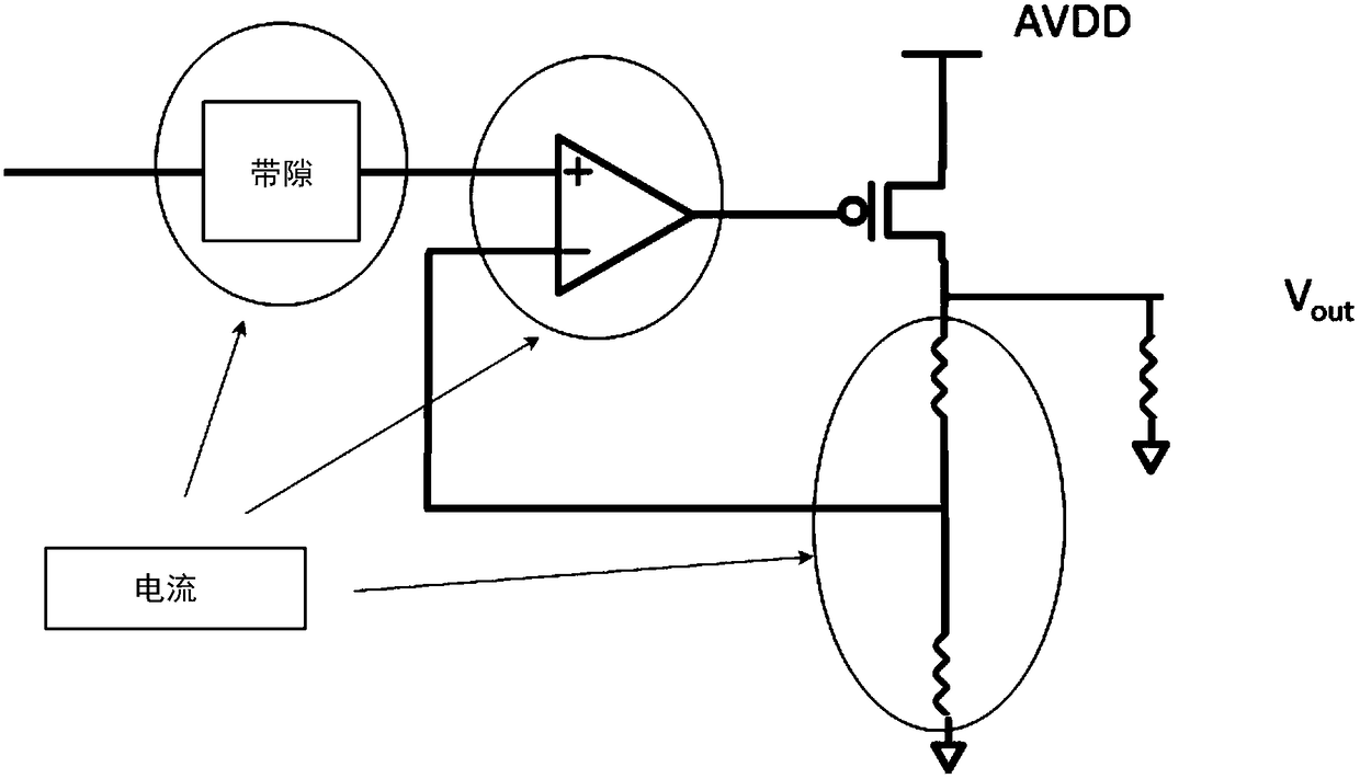
A voltage stabilizing circuit and a stable technology, applied in the direction of adjusting electrical variables, instruments, control/regulation systems, etc., can solve problems such as lengthening or shortening of output time, insufficient voltage drop of devices, etc., to avoid insufficient voltage drop and save power consumption Effect

Active Publication Date: 2019-01-18
SEMICON MFG INT (SHANGHAI) CORP +1
View PDF9 Cites 0 Cited by
  • Summary
  • Abstract
  • Description
  • Claims
  • Application Information

AI Technical Summary

Problems solved by technology

[0006] If a capacitor is used to stabilize the output, the output current will be affected by the device. If it is affected, the output time will be lengthened or shortened, resulting in insufficient voltage drop on the device.

Method used


Image

  • A voltage regulator circuit and electronic device
  • A voltage regulator circuit and electronic device
  • A voltage regulator circuit and electronic device

Examples


Embodiment 1

[0056] Figure 4 is a schematic block diagram of a voltage stabilizing circuit according to an embodiment of the present invention.

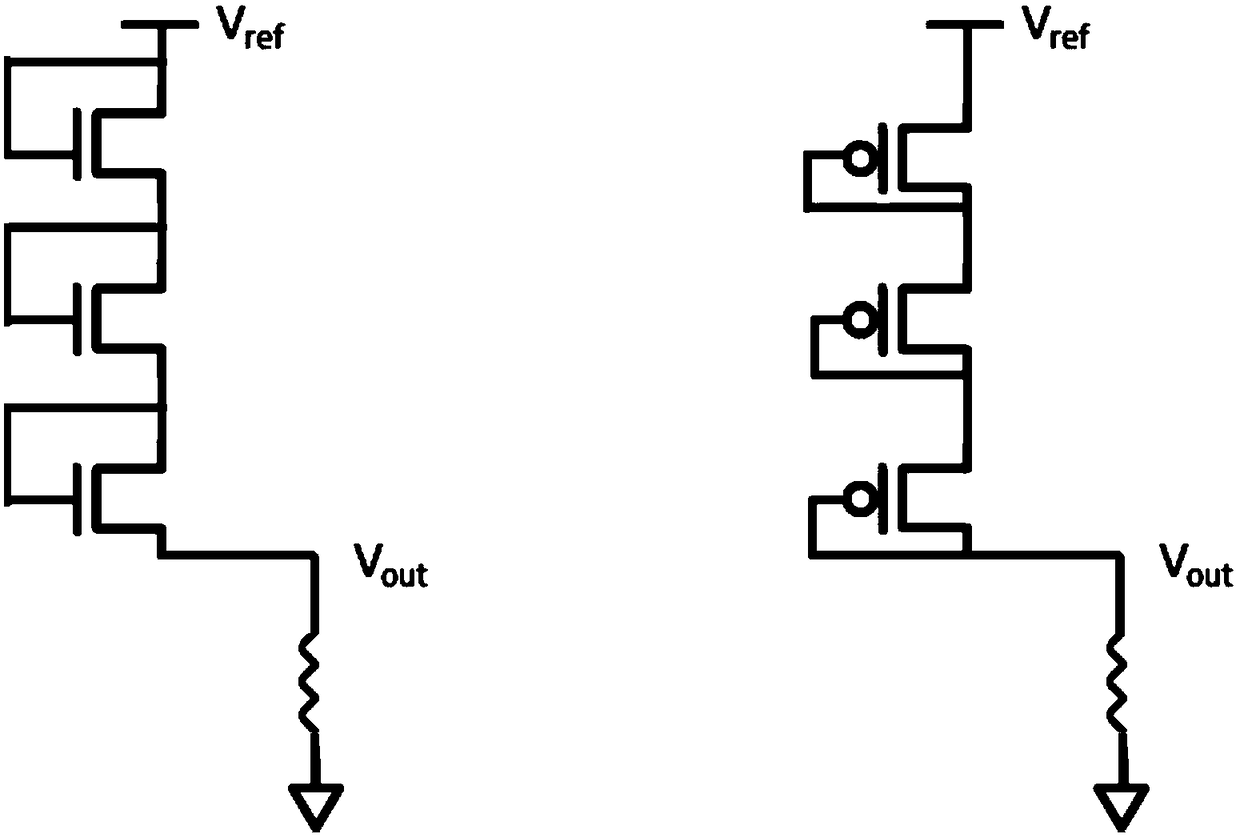
[0057] like Figure 4 As shown, the voltage regulator circuit is designed with three MOS connected in series. The clock signal is input to the test unit, wherein the test unit (ie, the stabilization unit) is mainly composed of an ALU and a control counter, and the test unit outputs control signals and output signals. Wherein, the output signal is connected to the switch, and the control signal is connected to the capacitor. The voltage stabilizing circuit in the embodiment of the present invention includes: a power supply unit and a stabilizing unit, the output terminal of the power supply unit is coupled to the voltage output terminal of the voltage stabilizing circuit through a controllable switch; the stabilizing unit includes: a control counting module , configured to calculate the time interval of the voltage detection performed on the v...

Embodiment 2

[0083] Still another embodiment of the present invention provides an electronic device, which includes the voltage stabilizing circuit described in the first embodiment.

[0084] Figure 7 is a schematic diagram of an electronic device according to an embodiment of the present invention. Figure 8 is another schematic diagram of an electronic device according to an embodiment of the present invention.

[0085] like Figure 7 and Figure 8 As shown, the electronic device of this embodiment can be a mobile phone (such as Figure 7 device 700 shown in ) and a tablet computer (such as Figure 8 device 800 shown in). In addition, the electronic device in this embodiment also includes, but is not limited to, any electronic product or device such as notebook computer, netbook, game console, TV, VCD, DVD, navigator, camera, video recorder, voice recorder, MP3, MP4, PSP, etc. , can also be any intermediate product including the semiconductor device.


PUM


Abstract

The invention provides a voltage stabilizing circuit and an electronic device; the voltage stabilizing circuit comprises a power supply unit and a stabilization unit; an output end of the power supply unit is coupled to a voltage output end of the voltage stabilizing circuit through a controllable switch; the stabilization unit comprises a counting control module which is configured to calculate the time interval for performing the voltage detection at the voltage output end; and a counting logic module which is configured to rewrite the count of a control counter on the basis of the change of the voltage detection results. The voltage stabilizing circuit of the present invention does not introduce direct current, thereby saving power consumption and obtaining a controllable output voltage, so as to avoid insufficient voltage drop on the device.

Description

technical field [0001] The invention relates to the field of semiconductors, and in particular, the invention relates to a voltage stabilizing circuit and an electronic device. Background technique [0002] The voltage required to maintain the data stored in the SRAM is very small, about 0.6v ~ 0.9v, and the required current is very small, about the order of uA level. In portable products, an LDO (Low Dropout Linear Regulator) is usually used to power the module. An LDO is a linear regulator that uses a transistor or FET operating in its linear region to subtract excess voltage from the applied input voltage to produce a regulated output voltage. The so-called drop voltage refers to the minimum value of the difference between the input voltage and the output voltage required by the regulator to maintain the output voltage within 100mV of its rated value. LDO (Low Dropout) regulators for positive output voltages typically use power transistors (also known as pass devices) a...

Claims


Application Information

Patent Timeline
Patent Type & Authority Patents(China)
IPC IPC(8): G05F1/10
CPCG05F1/10
Inventor 许瑜芳黄正乙杨家奇罗冬祥黄正太陈萍
Owner SEMICON MFG INT (SHANGHAI) CORP
Learn More