
Self-locking optoelectronic tweezer and its fabrication

A self-locking, optical tweezers technology, used in optics, dielectrophoresis, optical components, etc., can solve problems such as the inability to provide optical image clarity

Active Publication Date: 2017-10-13
RGT UNIV OF CALIFORNIA
View PDF3 Cites 3 Cited by
  • Summary
  • Abstract
  • Description
  • Claims
  • Application Information

AI Technical Summary

Problems solved by technology

However, such low numerical aperture lenses do not provide the required optical image sharpness to create light intensity gradients that produce sufficient trapping power

Method used


Image

  • Self-locking optoelectronic tweezer and its fabrication
  • Self-locking optoelectronic tweezer and its fabrication
  • Self-locking optoelectronic tweezer and its fabrication

Examples


Embodiment approach 1

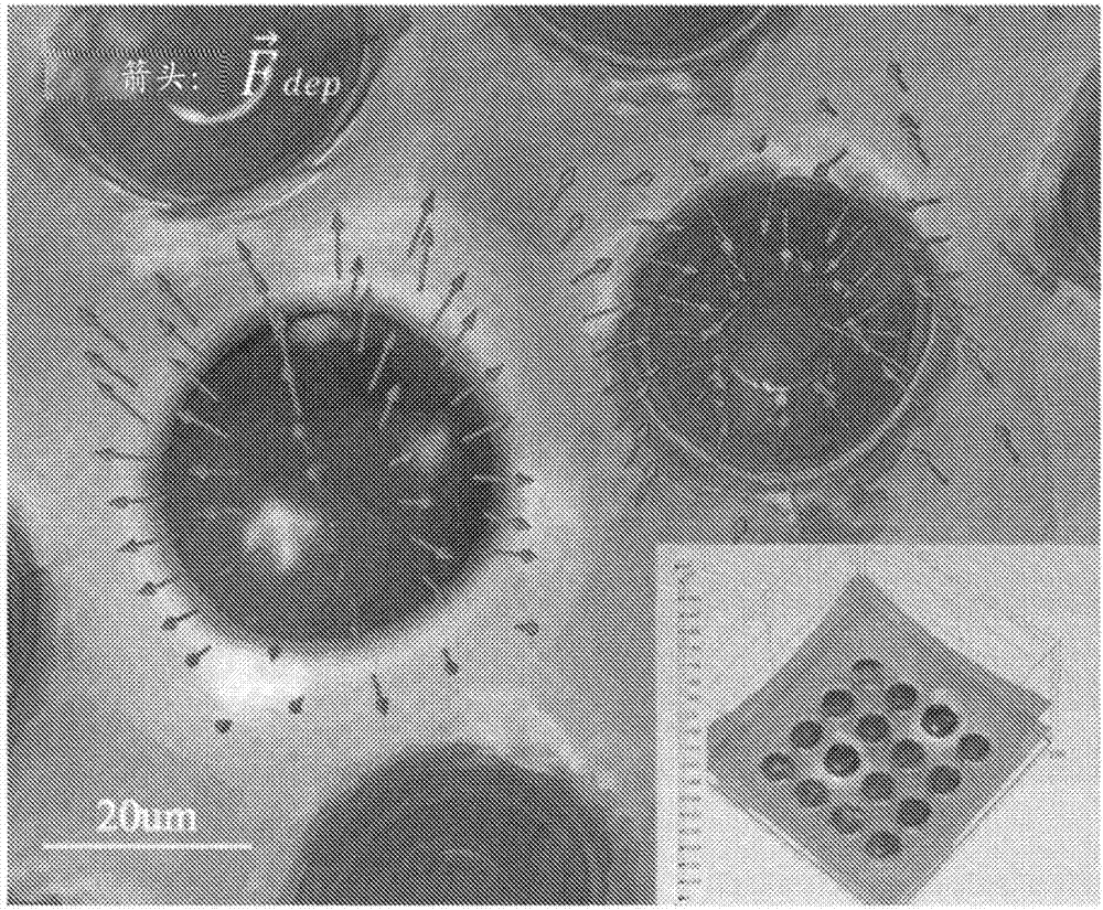
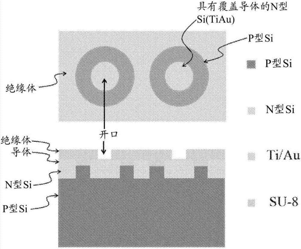
[0008] Embodiment 1: A self-locking photoelectric tweezers device, which includes: a first substrate, which includes a first electrode and a plurality of annular and / or non-circular phototransistors that can be optically turned on and off, wherein the The phototransistor and first substrate are configured to generate a negative dielectrophoretic (DEP) force at the annular or non-circular phototransistor when a voltage is applied to the device; a DEP at a ring-shaped or bean-shaped (eg, kidney bean-shaped) phototransistor; and a surface comprising a second electrode, wherein the surface is configured to define a chamber or channel between the first substrate and the surface , and the chamber or channel is configured to receive and, or hold, a fluid containing cells or particles.

Embodiment approach 2

[0009] Embodiment 2: The device of Embodiment 1, wherein the phototransistor is ring-shaped.

Embodiment approach 3

[0010] Embodiment 3: The device of Embodiment 1, wherein the non-circular phototransistor is bean-shaped (eg, kidney bean-shaped).


PUM

PropertyMeasurementUnit
Conductivityaaaaaaaaaa
Thicknessaaaaaaaaaa

Abstract

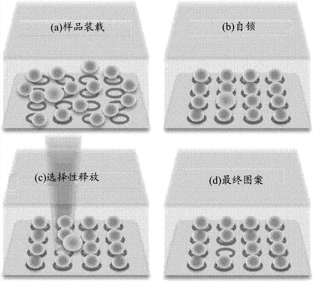
A novel self-locking optoelectronic tweezers (SLOT) for single microparticle manipulation across a large area is provided. DEP forces generated from ring-shape lateral phototransistors are utilized for locking single microparticles or cells in the dark state. The locked microparticles or cells can be selectively released by optically deactivating these locking sites.

Description

[0001] Cross References to Related Applications [0002] This application claims the benefit of and priority to USSN 62 / 038,150, filed August 15, 2014, and USSN 62 / 181,627, filed June 18, 2015, both of which are incorporated herein by reference in their entireties for all purposes. [0003] Statement of Government Funding [0004] This invention was made with government support under grant number 1232279 awarded by the National Science Foundation. The government has certain rights in this invention. Background technique [0005] Optical tweezers (OET) have been developed for parallel manipulation of single cells and particles for various biological applications (Chiou et al. (2005) Nature 436(7049):370-372.). For example optoelectronic tweezers (OET) have been developed for dynamic manipulation of single cells and particles (Chiou et al. (2005) Nature, 436(7049):370-372). OET can be used to trap and manipulate semiconductor and metallic nanowires (Jamshidi et al. (2008) Nat...

Claims


Application Information

Patent Timeline
IPC IPC(8): C12M1/42C12M3/00G01N21/01
CPCB01L3/502761G01N15/10G02B21/32G01N2035/1046B03C5/005B03C5/026B03C2201/26B01L3/502707B01L2200/0668B01L2400/0454B01L3/502715C12M1/42C12M3/00
Inventor 杨雅嘉毛宇飞培钰·E·邱徐志安
Owner RGT UNIV OF CALIFORNIA
Learn More