Optoelectric measuring device and method for measuring an electrical current

A technology for measuring devices and compensating currents, applied in measuring devices, measuring electrical variables, voltage/current isolation, etc., can solve problems such as limited precision, limited precision, and complicated precision, and achieve low cost, voltage isolation, and high measurement accuracy Effect

Inactive Publication Date: 2017-10-13
SIEMENS ENERGY GLOBAL GMBH CO & KG
View PDF3 Cites 6 Cited by
  • Summary
  • Abstract
  • Description
  • Claims
  • Application Information

AI Technical Summary

Problems solved by technology

[0003] A disadvantage of the known measuring devices is that the accuracy of the measurement of the polarization state, for example the polarization angle, which is usually carried out by means of an interferometer or a polarization analyzer, is relatively complex and has only a limited accuracy
This effect is ...

Method used


Image

  • Optoelectric measuring device and method for measuring an electrical current
  • Optoelectric measuring device and method for measuring an electrical current
  • Optoelectric measuring device and method for measuring an electrical current

Examples


Embodiment Construction

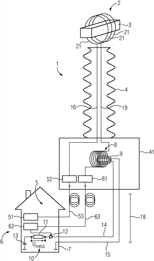
[0038] Accordingly, a schematic illustration of the measuring device 1 is shown in the drawing. The measuring device 1 comprises a Faraday sensor device 2 which is arranged in the vicinity of a high-voltage current conductor 3 . The Faraday sensor device 2 comprises a plurality of fiber optic windings 21 which are wound around the high-voltage current conductor 3 . In the variant shown here, the current conductor 3 is part of a high-voltage system (not shown).

[0039] The high voltage current conductor 3 is thus at a high voltage potential. For potential separation between the high-voltage potential and ground potential, an insulating element 4 is provided which extends between the high-voltage current conductor 3 and ground and is shown here in the form of a hollow insulator. The insulating element 4 also comprises an insulating body bottom 41 on which the insulating element 4 stands.

[0040] The measuring device 1 also includes a light source 5 . The light source 5 has...


PUM


Abstract

The invention relates to a measuring device (1) for measuring an electrical current, comprising a light source (5) for generating a polarised primary light signal for feeding into a Faraday sensor unit (2), and comprising a detector (6) for detecting a secondary light signal provided by the Faraday sensor unit (2) and polarisation-altered in relation to the primary light signal. The invention is characterised by an optical-electrical compensation element (8, 9, 10), by means of which the polarisation alteration of the secondary light signal can be compensated via an opposite polarisation alteration, and a measurement signal, according to the opposite polarisation alteration, for the electrical current can be deduced. The invention also relates to a method for measuring an electrical current by means of the measuring device (1).

Description

technical field [0001] The present invention relates to a measuring device for measuring current using a light source for generating a polarized main light signal to be fed into a Faraday sensor device and a detector for collecting the polarization changes relative to the main light signal provided by the Faraday sensor device secondary light signal. Background technique [0002] A measuring device of this type is known, for example, from EP 0 865 610 B1. The measurement of the current is based here on the so-called Faraday effect. The Faraday effect should be understood as the change in the refractive index of a particular material as a function of a magnetic field. This effect can be exploited to change the polarization state of light passing through the material. Especially in the case of linearly polarized light, this change rotates the plane of polarization of the light. The corresponding angle of rotation of the rotation is ideally proportional to the path integral...

Claims


Application Information

Patent Timeline
IPC IPC(8): G01R15/24
CPCG01R15/246G01R1/20G01R15/247
Inventor M.霍夫斯泰特尔D.埃尔金M.威尔施
Owner SIEMENS ENERGY GLOBAL GMBH CO & KG
Why Eureka
Try Eureka