Easy-to-install rotary cultivator cutter shaft assembly

A technology of rotary tiller and rotary tiller, which is applied in the fields of tillage implements, agricultural machinery and implements, etc. It can solve the problems of high material consumption, high manufacturing cost, and high technical requirements for shaft tube and shaft head welding.

Active Publication Date: 2017-10-17
亚澳南阳农机有限责任公司
View PDF7 Cites 1 Cited by
  • Summary
  • Abstract
  • Description
  • Claims
  • Application Information

AI Technical Summary

Problems solved by technology

The correct use and adjustment of the rotary tiller is very important to maintain its good technical state and ensure the quality of cultivation. The existing rotary machine with intermediate transmission structure has a transmission box in the middle and bearings at both ends of the rotary tiller shaft. Under the action of the bearings at both ends, the transmission box drives the rotary cultivator cutter shaft to rotate for farming. The rotary tiller cutter shaft assembly includes a cutter shaft and a rotary tiller. The cutter shaft includes a shaft body and a knife seat arranged on the outer surface of the shaft body. The rotary tiller is installed on the knife seat of the knife shaft. The shaft body structure and disadvantages of the existing knife shaft: it directly adopts the solid round steel structure. Shaft tube, two shaft heads are welded at both ends of the shaft tube, and bearings are installed on the shaft head. The disadvantage of this structure: the shaft tube and the shaft head have high welding technology requirements, and welding defects cannot be avoided. There is welding stress, which affects the overall service life of the cutter shaft. , and because the shaft tube and the shaft head are fixed together by welding, when the shaft tube or the shaft head needs to be replaced, they need to be replaced together, resulting in high manufacturing costs

Method used


Image

  • Easy-to-install rotary cultivator cutter shaft assembly
  • Easy-to-install rotary cultivator cutter shaft assembly
  • Easy-to-install rotary cultivator cutter shaft assembly

Examples


Embodiment Construction

[0017] The following will clearly and completely describe the technical solutions in the embodiments of the present invention with reference to the accompanying drawings in the embodiments of the present invention. Obviously, the described embodiments are only some, not all, embodiments of the present invention. Based on the embodiments of the present invention, all other embodiments obtained by persons of ordinary skill in the art without making creative efforts belong to the protection scope of the present invention.

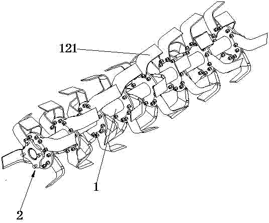
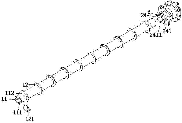
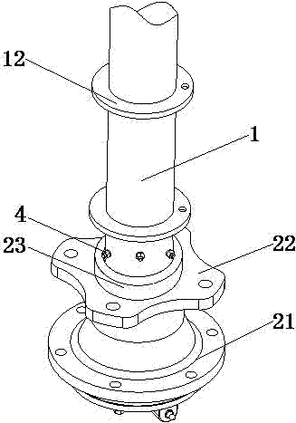
[0018] see Figure 1-4 As shown, the easy-to-install rotary tiller cutter shaft assembly of the present invention includes a shaft tube 1, and the two ends of the shaft tube 1 are provided with a tube through hole 11. The inside of the shaft tube 1 is a solid structure, and the outer wall of the shaft tube 1 The knife seat 12 is uniformly welded; the inner wall of the pipe through hole 11 is uniformly welded with an inner stopper 111, the inner stopper 111 is ...


PUM


Abstract

The invention discloses an easy-to-install rotary cultivator cutter shaft assembly comprising a shaft pipe. Two ends of the shaft pipe are provided with a pipe through hole; internal baffle blocks are evenly welded on the peripheral inner wall of the pipe through hole; thread holes are formed on the peripheral outer wall of the pipe through hole; an external ring sleeve and a fixing column are vertically welded in the center of the other side wall of a connection welding member; internal baffle grooves are evenly formed in the side wall of the fixing column; the internal baffle blocks are placed in the internal baffle grooves; and an end port of a bolt passes through the thread hole and extends to the through hole. A pipe orifice is right clamped in the annular groove, so weeds cannot enter a seam between the shaft head and the shaft pipe; weed winding can be avoided and service life of the cutter shaft can be prolonged; the shaft pipe is in a threaded connection with the shaft head; the structure can be conveniently assembled and disassembled and low manufacturing cost is achieved; a loose problem can be prevented; the internal baffle blocks are embedded into the internal baffle grooves; the rotary cutters are staggered, so soil-penetrating resistance of blades can be reduced; and the soil after the rotary cultivation cannot knot, so rotary cultivation effect can be greatly improved.

Description

technical field [0001] The invention relates to the technical field of agricultural machinery, in particular to an easy-to-install rotary tiller cutter shaft assembly. Background technique [0002] A rotary tiller is a tillage machine that is matched with a tractor to complete plowing and harrowing operations. It has been widely used because of its strong soil breaking ability and flat surface after plowing. At the same time, it can chop up the root stubble buried below the surface, which is convenient for the seeder to operate and provides a good seed bed for later sowing. The correct use and adjustment of the rotary tiller is very important to maintain its good technical state and ensure the quality of cultivation. The existing rotary machine with intermediate transmission structure has a transmission box in the middle and bearings at both ends of the rotary tiller shaft. Under the action of the bearings at both ends, the transmission box drives the rotary cultivator cutt...

Claims


Application Information

Patent Timeline
IPC IPC(8): A01B33/10
CPCA01B33/10
Inventor 隆成柱
Owner 亚澳南阳农机有限责任公司
Why Eureka
Try Eureka