Automatic welding method used for heat exchanger and device for automatic welding method

An automatic welding and heat exchanger technology, applied in welding equipment, arc welding equipment, metal processing equipment, etc., can solve problems such as unfavorable enterprise development, large number of defective products, easy positioning deviation, etc., and achieve fast and accurate positioning. Determining the effect of convenient, quick and efficient welding results

Active Publication Date: 2017-10-17
FOSHAN SHUNDE DISTRICT TUOQIU MINGXIN AIR - CONDITIONING HEAT PUMP IND CO LTD
8 Cites 3 Cited by

AI-Extracted Technical Summary

Problems solved by technology

Since the straight seam of the cylinder body, the circular seam of the cylinder head and the circular seam of the bottom seal of the existing cylindrical body prefabricated parts are all separate tooling, and each tooling needs to be manually repositioned and then welded, the operation is cumberso...

Abstract

The invention provides an automatic welding method used for a heat exchanger and a device for the automatic welding method. The device comprises a rack and at least one set of automatic tool device adaptively assembled on the rack. Each automatic tool device comprises an installation seat, a lifting part, a pushing part, a clamping part, a rotating part, a mechanical hand welding gun and a gas protection part. By means of the automatic tool devices, cylinder body longitudinal joints, cylinder body head sealing circular joints and cylinder body bottom sealing circular joints of heat exchange prefabricated parts can be automatically and continuously completed simply by positioning and installing tools at a time, positioning is fast and accurate, high efficiency is achieved, and the welding effect is good; and due to the cooperation of a limiting line, whether the heat exchange prefabricated parts are qualified or not after welding can be conveniently checked, judging is convenient and fast, and the machining quality is ensured.

Application Domain

Technology Topic

Image

  • Automatic welding method used for heat exchanger and device for automatic welding method
  • Automatic welding method used for heat exchanger and device for automatic welding method
  • Automatic welding method used for heat exchanger and device for automatic welding method

Examples

  • Experimental program(1)

Example Embodiment

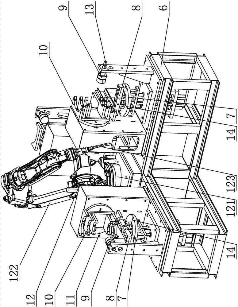
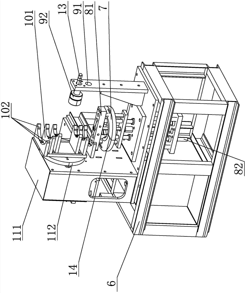
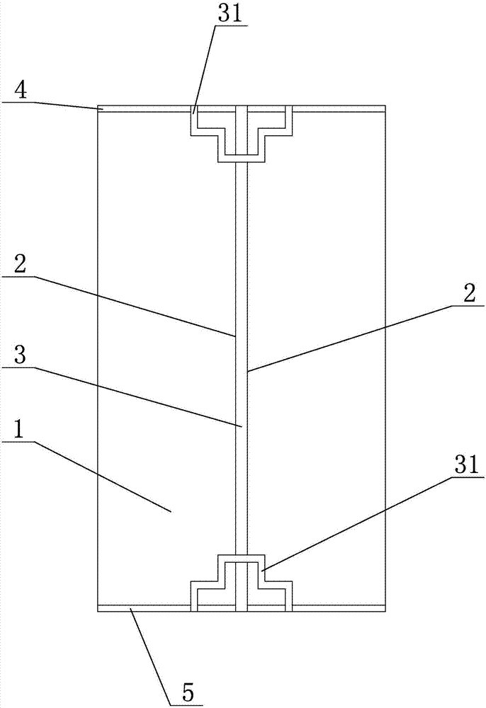
[0031] The present invention will be further described below in conjunction with the accompanying drawings, according to Figure 1 to Figure 5 As shown, in the automatic welding method for heat exchangers of the present invention, the heat exchanger includes a heat exchange preform 1, and the heat exchange preform 1 has a cylindrical straight seam 3, a cylindrical head circumferential seam 4, and a cylindrical bottom cover. Circumferential seam 5, the automatic welding method includes the following steps:
[0032] 1) Prepare limit line 2; prepare limit line 2 on both sides of the cylinder straight seam 3 of the heat exchange preform 1, on both sides of the cylinder head circumferential seam 4, and on both sides of the cylinder bottom cover circumferential seam 5 respectively .
[0033] 2) The heat exchange preform 1 is positioned on the tooling; the heat exchange preform 1 is installed on the tooling equipment, and the straight seam 3 of the cylinder body is docked with the positioning line 14 of the tooling equipment, and the tooling equipment lifts the heat exchange preform 1 to the designated position. Clamp after position. Subsequently, the positioning line 14 of the tooling equipment is pulled down; during this period, the heat exchange preform 1 is filled with protective gas and then stopped.
[0034] 3) Welding;
[0035] a: Welding the cylinder head circumferential seam 4; the manipulator welding torch 12 of the tooling equipment moves on the cylinder head circumferential seam 4 of the heat exchange preform 1 and on the cylinder head circumferential seam 4 under normal temperature and normal pressure Perform horizontal welding.
[0036] Wherein, the cylinder head circumferential seam 4 includes the inner circumferential seam 41 of the cylinder head, the middle circumferential seam 42 of the cylinder head, and the outer circumferential seam 43 of the cylinder head. Next, horizontally weld the inner circumferential seam 41 of the barrel head, the outer circumferential seam 43 of the barrel head, and the middle circumferential seam 42 of the barrel head in sequence.
[0037] b: Welding the circular seam 5 of the bottom cover of the cylinder body; after the welding of the circular seam 4 of the cylinder body head is completed, the tooling equipment drives the heat exchange preform 1 to rotate at a fixed angle, so that the circular seam 5 of the cylinder bottom cover of the heat exchange preform 1 rotates to the designated position ; Then, the manipulator welding torch 12 of the tooling equipment moves to the bottom cover circumferential seam 5 of the heat exchange preform 1 under normal temperature and pressure, and performs horizontal welding on the cylindrical bottom cover circumferential seam 5 .
[0038] Among them, the cylindrical bottom cover circumferential seam 5 includes the cylindrical body bottom cover inner circumferential seam 51, the cylindrical body bottom cover middle circumferential seam 52, and the cylindrical body bottom cover outer circumferential seam 53. The manipulator welding gun 12 equipped with the equipment sequentially seals the cylindrical body back under the condition of normal temperature and normal pressure. The inner circumferential seam 51, the outer circumferential seam 53 of the cylinder bottom cover, and the inner circumferential seam 52 of the cylindrical body bottom cover are horizontally welded.
[0039] c: Weld the straight seam 3 of the cylinder body; after the welding of the circular seam 5 of the bottom cover of the cylinder body, the tooling equipment drives the heat exchange preform 1 to rotate at a fixed angle, so that the cylinder body straight seam 3 of the heat exchange preform 1 rotates to the designated position; then, The manipulator welding torch 12 of the tooling equipment moves on the cylindrical straight seam 3 of the heat exchange preform 1 under the condition of normal temperature and normal pressure, and performs horizontal welding on the cylindrical straight seam 3 .
[0040]d: Welding reinforcement seam 31; after the welding of the straight seam 3 of the cylinder body is completed, the manipulator welding torch 12 of the tooling equipment moves to the front end and the rear end of the straight seam 3 of the cylinder body of the heat exchange preform 1 in turn under the condition of normal temperature and pressure, The front end and the rear end of the straight seam 3 of the cylindrical body are respectively welded horizontally with reinforcing seams 31 in sequence.
[0041] 4) At the end of welding, the shielding gas is filled with a certain amount and stopped at the end of welding; then, the tooling equipment is reset.
[0042] 5) After welding inspection, judge whether the welding seam is qualified according to the limit line 2.
[0043] That is, by using the positioning line 14 to connect with the straight seam 3 of the cylindrical body, the heat exchange preform 1 only needs to be positioned and installed on the tooling equipment once, and the cylindrical straight seam 3 and the cylindrical body of the heat exchange preform 1 can be automatically and continuously completed. The head girth seam 4 and the cylinder bottom girth seam 5 are fast and accurate in positioning, efficient and have good welding effect; and, with the setting of the limit line 2, it is convenient to check whether the post-weld heat exchange preform 1 is qualified or not, and it is convenient to judge. Fast, guaranteed processing quality.
[0044] refer to figure 1 and figure 2 As shown, the tooling equipment used in the heat exchanger automatic welding method of the present invention includes a frame 6 and at least one set of automatic tooling devices adapted and assembled on the frame 6 . The automatic tooling device of the present application is provided with three groups, and the automatic tooling devices of the three groups are such as figure 1 distributed. The automatic tooling device includes a mounting seat 7 , a lifting part 8 , a pushing part 9 , a clamping part 10 , a rotating part 11 , a robot welding torch 12 , and a gas shielding part 13 . Wherein, the mounting seat 7 is provided with a positioning line 14 which is vertically distributed with the welding position of the robot welding torch 12 . The lifting member 8 is fitted on the mounting seat 7 and moves up and down relative to the mounting seat 7 . The clamping part 10 is adapted to be installed on the rotating part 11 , the rotating part 11 is located above the mounting seat 7 and rotates vertically relative to the welding position of the robot welding torch 12 , and the gas shielding part 13 is adapted to be installed on the pushing part 9 .
[0045] refer to figure 1 and figure 2 As shown, the lift member 8 includes a lift table 81 and a lift drive cylinder 82 . The cylinder body of the lift driving cylinder 82 is fixedly installed on the frame 6 , and the push rod of the lift driving cylinder 82 is connected to the lift table 81 and drives the lift table 81 to move up and down relative to the mounting base 7 . The height pushed up by the push rod of the lift driving cylinder 82 is the height at which the customized heat exchange preform 1 is welded.
[0046] refer to figure 1 and figure 2 As shown, the pushing member 9 includes a support frame 91 and a pushing driving rod 92 . The gas protection component 13 is fitted and installed on the support frame 91 , the support frame 91 is in front of the mounting seat 7 , and the push drive rod 92 is fitted on the end of the support frame 91 and moves relative to the jaw position of the clamping member 10 . The heat exchange preform 1 on the lifting platform 81 is pushed to the clamping member 10 by the pushing member 9 . Wherein, the push driving rod 92 of the push member 9 may be provided with a protective soft cover for protecting the heat exchange preform 1 to protect the heat exchange preform 1 .
[0047] refer to figure 1 As shown, the clamping member 10 includes a clamping driving member 101 that can be opened and has three positioning protrusions 102. The three positioning protrusions 102 are distributed at both ends and the middle of the circular arc portion of the clamping driving member 101, so The clamping drive 101 is adapted to be mounted on the indexer or servo motor 112 of the rotating part 11 and rotates along with the indexer or servo motor 112 .
[0048] refer to figure 1 and figure 2 As shown, the rotating part 11 includes a fixed seat 111 and an indexer or a servo motor 112 . The fixed seat 111 is installed on the frame 6 , and the indexer or the servo motor 112 is adapted to be installed on the fixed seat 111 and rotates vertically relative to the welding position of the robot welding torch 12 . The indexer or servo motor 112 rotates vertically relative to the welding position of the robot welding torch 12 for at least four times. In the present application, the indexer or servo motor 112 rotates vertically relative to the welding position of the robot welding torch 12 for 4 times, and each time rotates 90 degrees, thereby driving the heat exchange preform 1 to rotate relative to the robot welding torch 12 to continuously complete the cylinder. Welding of straight seam 3, circular seam 4 of cylinder head, and circular seam 5 of cylinder bottom.
[0049] refer to figure 1 and figure 2 As shown, the robotic welding torch 12 includes a rotary drive base 121 , a robotic arm 122 , and a welding torch 123 . The rotary drive base 121 is adapted to be installed on the frame 6 and rotates relative to the frame 6 , the mechanical arm 122 is adapted to be installed on the rotary drive base 121 and rotates with the rotary drive base 121 , and the welding gun 123 is adapted to be installed on the mechanical arm 122 . The swing end can move linearly or circularly with the swing end of the mechanical arm 122 . That is, by using the rotary drive seat 121, the mechanical arm 122 can be driven to rotate to each group of automatic tooling devices, and the heat exchange preforms 1 of each group of automatic tooling devices can be continuously welded, so as to realize batch welding processing and ensure the welding effect. .
[0050] refer to Figure 1 to Figure 5 As shown, the working principle and working process of the automatic welding tooling equipment for heat exchangers are as follows:
[0051] First, install the heat exchange preform 1 on the mounting seat 7, and then connect the cylindrical straight seam 3 of the heat exchange preform 1 with the positioning line 14 on the mounting seat 7, so as to effectively ensure the straight seam 3 of the cylindrical body and the welding track. consistency.
[0052] Then, the automatic tooling device operates, the push rod of the lift driving cylinder 82 pushes the lift table 81 to rise, and the lift table 81 drives the heat exchange preform 1 to rise. In practical applications, the lifting height of the lifting platform 81 can be adjusted to ensure that the circumferential seam 4 of the cylinder head and the circumferential seam 5 of the bottom of the cylinder are respectively consistent with the welding trajectory.
[0053] After rising to the designated position, the push drive lever 92 is activated. The push driving rod 92 moves forward and pushes the heat exchange preform 1 , so that the heat exchange preform 1 is pushed to the jaw position of the clamping part 10 . The clamping part 10 operates, and the clamping drive 101 of the clamping part 10 clamps the heat exchange preform 1 . Because the clamping driving member 101 has three positioning protrusions 102, the three positioning protrusions 102 are distributed at both ends and the middle of the circular arc portion of the clamping driving member 101, thereby realizing the positioning and operation of the center of the heat exchange preform 1 determined by three points. The center of the track is the same, and it also ensures that the heat exchange preform 1 will not fall off during rotation, which enhances the running stability and ensures the processing quality of the product.
[0054] At this time, the push rod of the elevating drive cylinder 82 is lowered and reset, and the push drive rod 92 is moved backward and reset. The effective movement space is given back, so that the heat exchange preform 1 can have a rotation space, so as to ensure that the heat exchange preform 1 corresponds to the horizontal welding angle requirement of the welding torch 123 .
[0055] Then, the robot torch 12 operates. The robotic arm 122 drives the welding torch 123 to perform horizontal welding on the circumferential seam 4 of the cylinder head. During this period, the welding torch 123 horizontally welds the inner circumferential seam 41 of the barrel head, the outer circumferential seam 43 of the barrel head, and the middle circumferential seam 42 of the barrel head in sequence, effectively cooling the inner circumferential seam 41 of the barrel head and the outer ring of the barrel head Over-temperature welding occurs between the seams 43 to avoid welding occlusion.
[0056] After the cylinder head girth 4 is welded, the robotic arm 122 drives the welding torch 123 to reset, and the indexer or servo motor 112 drives the clamping part 10 to rotate 180 degrees, so that the cylinder bottom girth 5 rotates to the designated position.
[0057] The robotic arm 122 drives the welding torch 123 to perform horizontal welding on the circumferential seam 5 of the bottom cover of the cylinder. During this period, the welding torch 123 horizontally welds the inner circumferential seam 51 of the cylindrical body bottom cover, the outer circumferential seam 53 of the cylindrical body bottom cover, and the middle circumferential seam 52 of the cylindrical body bottom cover, effectively cooling the inner circumferential seam 51 of the cylindrical body bottom cover and the outer circumferential seam 53 of the cylindrical body bottom cover. Warm welding to avoid welding occlusion.
[0058] After the circular seam 5 on the bottom cover of the cylinder body is welded, the robot arm 122 drives the welding torch 123 to reset, and the indexer or servo motor 112 drives the clamping part 10 to rotate 90 degrees, so that the straight seam 3 of the cylinder body rotates to the designated position.
[0059] The robotic arm 122 drives the welding torch 123 to move and weld in a straight line while maintaining a horizontal state on the straight seam 3 of the cylinder. Subsequently, the robotic arm 122 drives the welding torch 123 to reset to the front end of the straight seam 3 of the cylinder body, and horizontally welds the reinforcement seam 31 at the front end of the straight seam 3 of the cylindrical body; The end welding strengthens the seam 31.
[0060] Then, the robotic arm 122 drives the welding torch 123 to reset, and at the same time, the indexer or the servo motor 112 drives the clamping part 10 to rotate 180 degrees, so that the straight seam 3 on the other side of the cylinder rotates to the designated position. Similarly, the straight seam 3 and the reinforcing seam 31 on the other side of the cylinder body are welded by the welding torch 123 . In this way, the processing of a heat exchange preform 1 is completed. Immediately, the rotary drive base 121 drives the mechanical arm 122 to rotate to the next group of automatic tooling devices to process the next heat exchange preform 1 .
[0061] It is worth noting that during welding, the welding torch 123 is always horizontally welded on the straight seam 3 of the cylinder body, the circumferential seam 4 of the cylinder head, and the circular seam 5 of the bottom cover of the cylinder, and the welding angle of the welding torch 123 is perpendicular to the welded heat exchange preform 1 . On the basis of the level of the welding process, adjust the welding operation angle according to the requirements of the welding process to ensure the welding quality.
[0062] The above-mentioned specific embodiments are only specific implementations of the present invention with better effects, and all automatic welding methods and equipment for heat exchangers with the same or equivalent structure as those of the present invention are all within the protection scope of the present application.

PUM

no PUM

Description & Claims & Application Information

We can also present the details of the Description, Claims and Application information to help users get a comprehensive understanding of the technical details of the patent, such as background art, summary of invention, brief description of drawings, description of embodiments, and other original content. On the other hand, users can also determine the specific scope of protection of the technology through the list of claims; as well as understand the changes in the life cycle of the technology with the presentation of the patent timeline. Login to view more.

Similar technology patents

Portable electric soldering iron

Owner:杭州致知科教用品有限公司

Classification and recommendation of technical efficacy words

Why Eureka
Try Eureka