
Device and method for measuring diameter of eccentric shaft of industrial robot joint decelerator

A technology of joint reducer and industrial robot, which is applied to measurement devices, optical devices, instruments, etc., can solve the problems of lack of versatility, large measurement error, low measurement efficiency, etc., and achieve the effect of accurate and reliable measurement values.

Active Publication Date: 2017-10-17
XI AN JIAOTONG UNIV
View PDF6 Cites 8 Cited by
  • Summary
  • Abstract
  • Description
  • Claims
  • Application Information

AI Technical Summary

Problems solved by technology

However, in actual production, the gap between the measuring sensor of the pneumatic measuring instrument and the outer surface of the workpiece to be measured is very small, resulting in a small measuring range of the pneumatic measuring instrument, which is suitable for the measurement process of a single-size workpiece and is not universal
When using a pneumatic measuring instrument to measure the eccentric shaft, the measurement of the eccentric shaft of different specifications requires corresponding mechanical adjustment of the sensor position, the measurement efficiency is low, and a large measurement error will be introduced
Therefore, in the process of measuring the diameter of eccentric shafts with multiple specifications and large batches, it is not suitable to use pneumatic measuring instruments

Method used


Image

  • Device and method for measuring diameter of eccentric shaft of industrial robot joint decelerator
  • Device and method for measuring diameter of eccentric shaft of industrial robot joint decelerator
  • Device and method for measuring diameter of eccentric shaft of industrial robot joint decelerator

Examples


Embodiment Construction

[0054] In describing the present invention, it is to be understood that the terms "upper", "lower", "front", "rear", "top", "bottom", "inner", "outer" etc. indicate an orientation or position The relationship is based on the orientation or positional relationship shown in the drawings, and is only for the convenience of describing the present invention and simplifying the description, rather than indicating or implying that the referred device or element must have a specific orientation, be constructed and operated in a specific orientation, therefore It should not be construed as a limitation of the present invention. In addition, the terms "first" and "second" are used for descriptive purposes only, and cannot be interpreted as indicating or implying relative importance or implicitly specifying the quantity of indicated technical features. Thus, a feature defined as "first" and "second" may explicitly or implicitly include one or more of these features. In the description o...


PUM


Abstract

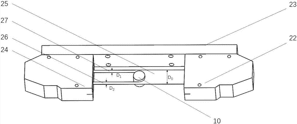
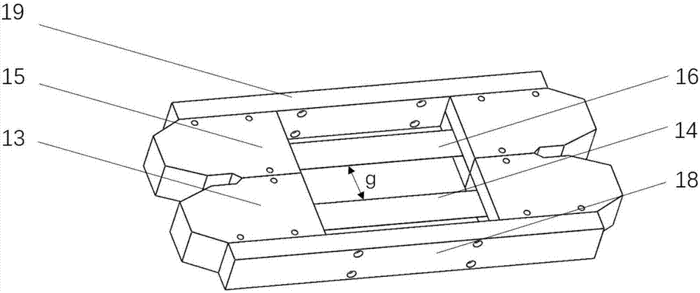
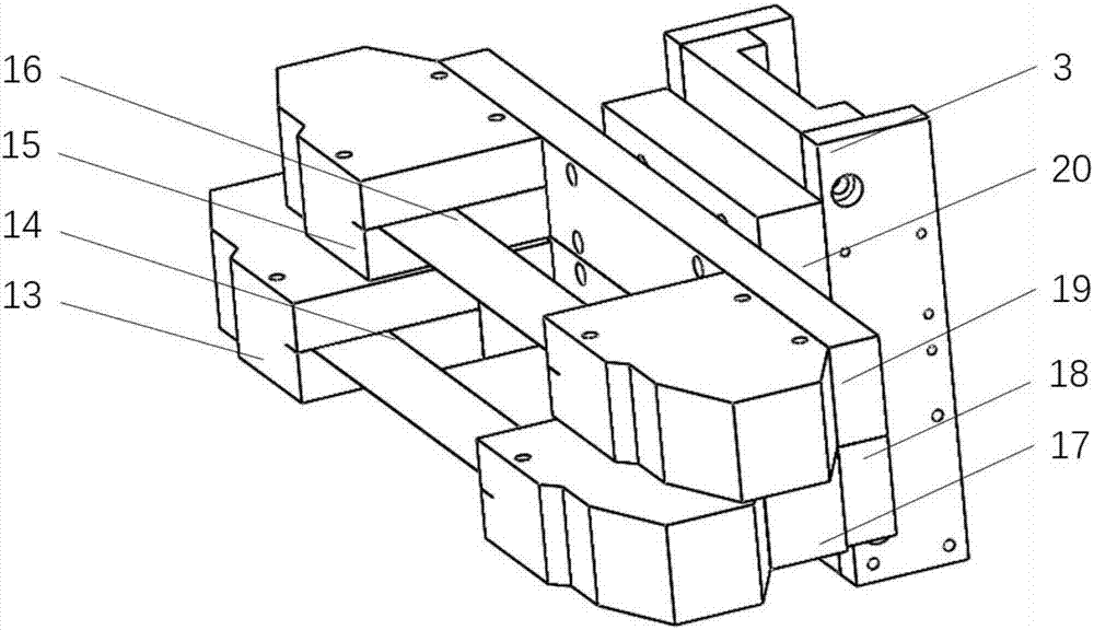
The invention discloses a device and method for measuring the diameter of an eccentric shaft of an industrial robot joint decelerator, and the device comprises a working platform, a central measurement vertical column, an upper tip unit, a lower tip unit, and a to-be-measured workpiece. The central measurement vertical column is disposed on the working platform, and the upper tip unit is connected with the central measurement vertical column through an upper tip moving sliding plate. The working platform is provided with a rotating tilt cylinder unit which is used for fixing the lower tip unit. The to-be-measured workpiece is clamped and located through the upper and lower tip units, and the upper tip moving sliding plate is provided with a staggered-type combined light curtain sensor measurement unit for measurement. The device employs a non-contact shaft diameter measurement method based on a light curtain sensor, can achieve the automatic measurement of the diameters of a plurality of types of eccentric shafts without the adjustment of the mechanical structure, and meets the demands of the measurement of the diameters of the plurality of types of eccentric shafts in the industrial production.

Description

technical field [0001] The invention belongs to the technical field of measuring the eccentric shaft of a reducer, and in particular relates to a device and a method for measuring the shaft diameter of an eccentric shaft of an industrial robot joint reducer. Background technique [0002] As the core component of the industrial robot reducer, the eccentric shaft is responsible for the power and torque transmission of the reducer, and its machining accuracy directly affects the transmission accuracy and comprehensive performance indicators of the reducer. Therefore, it is very important for the production and assembly of the reducer to accurately measure the diameter of the eccentric shaft and separate the unqualified workpieces in time. [0003] In the industrial production process, commonly used shaft diameter measuring instruments are: vernier calipers, pneumatic measuring instruments, and outer diameter measuring instruments. [0004] The vernier caliper is a traditional ...

Claims


Application Information

Patent Timeline
IPC IPC(8): G01B11/10
CPCG01B11/105
Inventor 李兵程凯孙彬侯颖李应飞陈磊魏翔
Owner XI AN JIAOTONG UNIV
Learn More