
A heat map generation method and device based on video analysis

A technology of video analysis and heat map, applied in still image data indexing, still image data retrieval, instruments, etc. Good effect, clear heat map effect

Active Publication Date: 2020-09-01
JINAN JOVISION TECH CO LTD
View PDF11 Cites 0 Cited by
  • Summary
  • Abstract
  • Description
  • Claims
  • Application Information

AI Technical Summary

Problems solved by technology

[0005] 1. In the existing technology, the method of directly superimposing the heat map on the moving target does not distinguish between the status of people staying and passing by, which will have a great impact on the accuracy of the heat map, especially if there are corridors, aisles, etc. in the scene The area where passenger flow must pass;
[0006] 2. Some heat map generation tools in the prior art have low algorithm efficiency, the background of the generated heat map is blurred, the visual effect is not good, and the implementation is complicated

Method used


Image

  • A heat map generation method and device based on video analysis
  • A heat map generation method and device based on video analysis
  • A heat map generation method and device based on video analysis

Examples


Embodiment 1

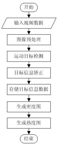
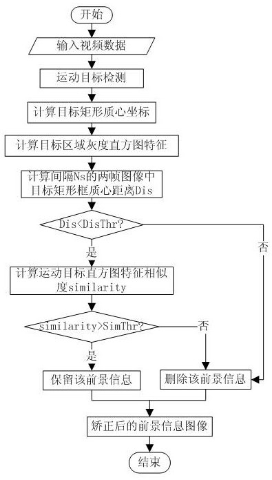
[0044] A heat map generation method based on video analysis. This method can read the video captured by the camera in real time, or it can be a saved video file; The length is corrected for the target information; then, the corrected target information is statistically generated to generate a density map; finally, the background image is rendered according to the density map to generate a heat map. as attached figure 1 As shown, this embodiment includes the following steps:

[0045] S11, video image acquisition

[0046] Input the video data to be detected. Assuming that the incoming video data is in YUV format, each frame of image in the video can be detected. The heat map is an estimate of the density of people over a period of time. In order to reduce the amount of calculation, it can also be According to the actual situation, the original video is down-sampled and then detected. In this embodiment, one image is processed every 1s.

[0047] S12. Video image preprocessing ...

Embodiment 2

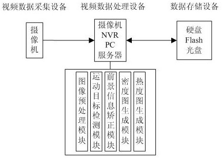
[0080] This embodiment provides a device for realizing the heat map generation method in Embodiment 1, as shown in the attached image 3 As shown, the device includes:

[0081] Video data collection equipment is all equipment that can collect video images, and is used to collect video image data, including but not limited to network video cameras, and what this embodiment uses is network video cameras;

[0082] The video data processing equipment can be a video camera (IPC), a network video recorder (NVR), a PC, a server, etc., and is used to obtain a density map after extracting a moving target, and generate a heat map according to the density map. This embodiment uses a video camera (IPC) and network video recorder (NVR) combined;

[0083] The data storage device is used to store the cumulative graph data information, which can be a hard disk, FLASH, optical disc, etc., and a digital hard disk is used in this embodiment.

[0084] The processing procedure in the video data ...


PUM


Abstract

The invention discloses a heat map generation method based on video analysis, which belongs to the field of intelligent monitoring. This method can read the video captured by the camera in real time or the saved video file; first, detect the moving target in the video scene image, and correct the target information according to the length of time the target stays; then, correct the target The information is statistically generated to generate a density map; finally, the background image is rendered according to the density map to generate a heat map. The present invention can realize the statistics and display of passenger flow density in monitoring scenes such as shopping malls and supermarkets, effectively eliminate the influence caused by frequent passing by rather than staying, and use different colors to represent the crowd density in different areas within a period of time to generate a heat map. Visually display the density distribution of the crowd, which is convenient for managers to grasp the distribution status of passenger flow in different target areas at different times.

Description

technical field [0001] The invention belongs to the field of intelligent monitoring, in particular to a method and device for generating a heat map based on video analysis. Background technique [0002] Heat map can very intuitively present some data that is not easy to understand or express, such as density, frequency, temperature, etc., by using regions and colors to present them in a way that is easier for people to understand. The heat map is actually a bird's-eye view of 3D visualization, and the color represents a dimension. In commercial applications, such as shopping malls, supermarkets, and convenience stores, the distribution of personnel in different areas in the same time period is different, and the distribution of personnel in different time periods in the same area is also different. How to enable managers to grasp the rules of customers' stay status at a glance , that is, the distribution of personnel in different areas in a certain period of time, based on ...

Claims


Application Information

Patent Timeline
Patent Type & Authority Patents(China)
IPC IPC(8): G06F16/51G06K9/00G06K9/32G06K9/62
CPCG06F16/51G06V20/52G06V10/25G06F18/22
Inventor 李铭刘琛尹萍刘爱玲王正彬邢新智
Owner JINAN JOVISION TECH CO LTD
Learn More